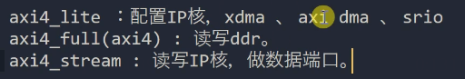
一、AXI 相关知识介绍
https://download.csdn.net/download/mvpkuku/90841873 AXI_LITE
选出部分重点,详细文档见上面链接。
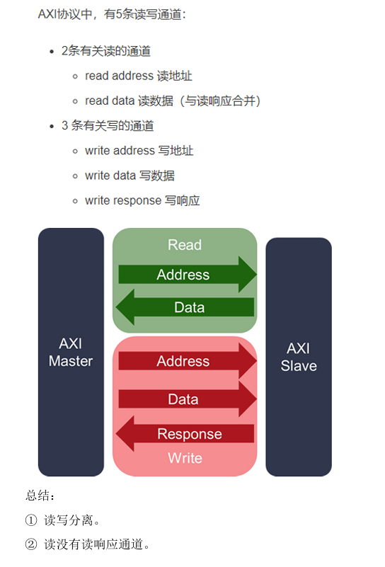
1.AXI4 协议类型
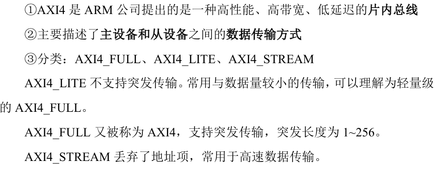
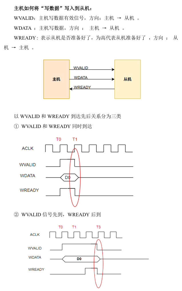
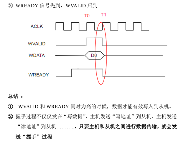
2.握手机制
二、AXI_LITE 协议的实现
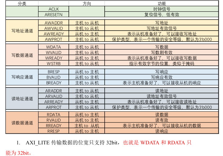
1. AXI_LITE 通道及各通道端口功能介绍
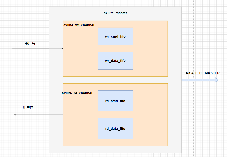
2.实现思路及框架
2.1 总体框架
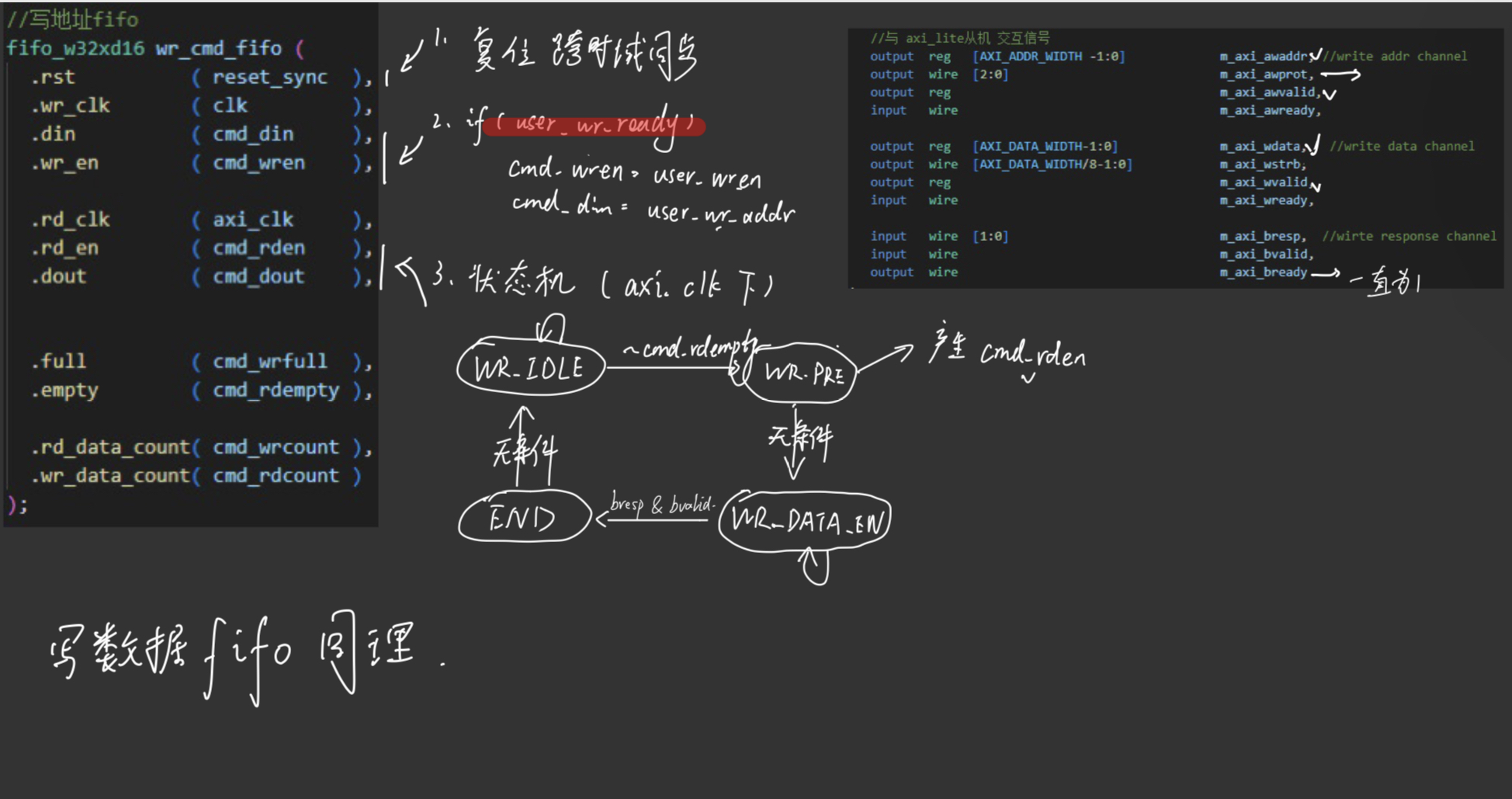
2.2 写通道
1.复位信号进行跨时钟域同步(用户时钟/AXI4时钟)
2.仅当user_wr_ready为高时,用户的写通道是有效的
3.例化两个fifo分别存储用户端传来的地址以及数据用户时钟写入,并通过AXI时钟读出
4.控制AXI_LITE(状态机)接口信号是在AXI时钟下进行 (控制cmd_rden/data_rden并输出对应的相关接口数据)
`timescale 1ns / 1ps
//
// Description: AXI_lite写通道
//
module axlite_wr_channel#(
	parameter USER_WR_DATA_WIDTH    = 32 ,//用户写数据位宽和AXI4—Lite数据位宽保持一致
	parameter AXI_DATA_WIDTH 		= 32, //AXI4_LITE总线规定,数据位宽只支持32Bit或者64bit
	parameter AXI_ADDR_WIDTH        = 32
)(
    input   wire							        clk,     //用户写时钟
	input   wire									axi_clk, //从机读时钟
	input   wire									reset,
    //与 用户端 交互信号
    input   wire								    user_wr_en,
	input   wire  [USER_WR_DATA_WIDTH-1:0]	        user_wr_data,
	input   wire  [AXI_ADDR_WIDTH-1 :0]		        user_wr_addr,
	output  wire                                    user_wr_ready,
    //与 axi_lite从机 交互信号
    output  reg   [AXI_ADDR_WIDTH -1:0]  	        m_axi_awaddr, //write addr channel
	output  wire  [2:0] 				 	        m_axi_awprot,
	output  reg   		 				 	        m_axi_awvalid,
	input   wire    		 			 	        m_axi_awready,

	output  reg   [AXI_DATA_WIDTH-1:0]	 	        m_axi_wdata,   //write data channel
	output  wire  [AXI_DATA_WIDTH/8-1:0] 	        m_axi_wstrb,
	output  reg      					 	        m_axi_wvalid,
	input   wire    					 	        m_axi_wready,

	input   wire  [1:0]	         	                m_axi_bresp,  //wirte response channel
	input   wire	   			         	        m_axi_bvalid,
	output  wire    			         	        m_axi_bready
);

(* dont_touch = "true"*) reg reset_sync_d0;  //user clk
(* dont_touch = "true"*) reg reset_sync_d1;
(* dont_touch = "true"*) reg reset_sync;
(* dont_touch = "true"*) reg a_reset_sync_d0; //axi clk
(* dont_touch = "true"*) reg a_reset_sync_d1;
(* dont_touch = "true"*) reg a_reset_sync;

reg	 [31:0]  cmd_din;
reg          cmd_wren;
wire [31:0]  cmd_dout;
reg 		 cmd_rden;
wire		 cmd_wrfull ;
wire		 cmd_rdempty;
wire [4:0]   cmd_wrcount;
wire [4:0]   cmd_rdcount;


reg	 [31:0]  data_din;
reg          data_wren;
wire [31:0]  data_dout;
reg 		 data_rden;
wire		 data_wrfull;
wire		 data_rdempty;
wire [4:0]   data_wrcount;
wire [4:0]   data_rdcount;

reg [2 : 0]	 cur_status;
reg [2 : 0]	 nxt_status;

localparam WR_IDLE     = 3'b000;
localparam WR_PRE      = 3'b001;
localparam WR_DATA_EN  = 3'b010;
localparam WR_END      = 3'b100;
/*--------------------------------------------------*\
				     assign
\*--------------------------------------------------*/
assign m_axi_bready  = 1'b1;
assign m_axi_awprot  = 0;
assign m_axi_wstrb   = {AXI_DATA_WIDTH/8{1'b1}};

assign user_wr_ready = reset_sync ? 1'b0 : cmd_wrcount <= 'd12 ; //留一点余量
                                                                 //当user_wr_ready为低的时候,用户发送写是无效的
/*--------------------------------------------------*\
				     CDC process
\*--------------------------------------------------*/
always @(posedge clk) begin
	reset_sync_d0   <= reset;
	reset_sync_d1   <= reset_sync_d0;
	reset_sync      <= reset_sync_d1;
end

always @(posedge axi_clk) begin
	a_reset_sync_d0 <= reset;
	a_reset_sync_d1 <= a_reset_sync_d0;
	a_reset_sync    <= a_reset_sync_d1;
end

/*--------------------------------------------------*\
    wirte addr to cmd fifo、write data to data fifo
\*--------------------------------------------------*/
always @(posedge clk) begin
	if (user_wr_ready) begin
		cmd_wren  <= user_wr_en;
		cmd_din   <= user_wr_addr;
		data_wren <= user_wr_en;
		data_din  <= user_wr_data;
	end
	else begin
		cmd_wren  <= 0;
		cmd_din   <= 0;
		data_wren <= 0;
		data_din  <= 0;
	end
end

/*--------------------------------------------------*\
	            WR state machine  (三段式)
\*--------------------------------------------------*/
always@(posedge axi_clk)begin
    if(a_reset_sync)
        cur_status <= WR_IDLE;
    else
        cur_status <= nxt_status;
end

always@(*)begin
    if(a_reset_sync)begin
        nxt_status <= WR_IDLE;
    end
    else begin
        case(cur_status)
            WR_IDLE : begin
                if(!cmd_rdempty)
                    nxt_status <= WR_PRE;
                else
                    nxt_status <= cur_status;
            end
            WR_PRE : begin
                nxt_status <= WR_DATA_EN;
            end
            WR_DATA_EN : begin
				if (m_axi_bvalid && m_axi_bready)
					nxt_status <= WR_END;
				else
					nxt_status <= cur_status;
			end
            WR_END : begin
				nxt_status <= WR_IDLE;
			end
            default : nxt_status <= WR_IDLE;
        endcase
    end
end
/*-----------------------------------------------------------*\
       read addr from cmd_fifo 、 read data from data_fifo
\*-----------------------------------------------------------*/
always @(*) begin
	if (a_reset_sync) begin
		cmd_rden   <= 0;
		data_rden  <= 0;
	end
	else begin
		cmd_rden   <= cur_status == WR_PRE;
		data_rden  <= cur_status == WR_PRE;
	end
end

always @(posedge axi_clk) begin
	if (cmd_rden)
		m_axi_awaddr <= cmd_dout;
	else
		m_axi_awaddr <= m_axi_awaddr;
end

always @(posedge axi_clk) begin
	if (a_reset_sync)
		m_axi_awvalid <= 0;
	else if (cur_status == WR_PRE)
		m_axi_awvalid <= 1'b1;
	else if (m_axi_awvalid && m_axi_awready)
		m_axi_awvalid <= 0;
end

always @(posedge axi_clk) begin
	if (data_rden)
		m_axi_wdata <= data_dout;
	else
		m_axi_wdata <= m_axi_wdata;
end

always @(posedge axi_clk) begin
	if (a_reset_sync)
		m_axi_wvalid <= 0;
	else if (cur_status == WR_PRE)
		m_axi_wvalid <= 1'b1;
	else if (m_axi_wvalid && m_axi_wready)
		m_axi_wvalid <= 0;
end


//写地址fifo
fifo_w32xd16 wr_cmd_fifo (
  .rst          ( reset_sync  ), // input wire rst
  .wr_clk       ( clk         ), // input wire wr_clk         用户写时钟
  .din          ( cmd_din     ), // input wire [31 : 0] din
  .wr_en        ( cmd_wren    ), // input wire wr_en

  .rd_clk       ( axi_clk     ), // input wire rd_clk         从机读时钟
  .rd_en        ( cmd_rden    ), // input wire rd_en
  .dout         ( cmd_dout    ), // output wire [31 : 0] dout


  .full         ( cmd_wrfull  ), // output wire full
  .empty        ( cmd_rdempty ), // output wire empty

  .rd_data_count( cmd_wrcount ), // output wire [4 : 0] rd_data_count
  .wr_data_count( cmd_rdcount )  // output wire [4 : 0] wr_data_count
);


//写数据fifo
fifo_w32xd16 wr_data_fifo (
  .rst          ( reset_sync   ), // input wire rst
  .wr_clk       ( clk          ), // input wire wr_clk        用户写时钟
  .din          ( data_din     ), // input wire [31 : 0] din
  .wr_en        ( data_wren    ), // input wire wr_en

  .rd_clk       ( axi_clk      ), // input wire rd_clk        从机读时钟
  .rd_en        ( data_rden    ), // input wire rd_en
  .dout         ( data_dout    ), // output wire [31 : 0] dout

  .full         ( data_wrfull  ), // output wire full
  .empty        ( data_rdempty ), // output wire empty

  .rd_data_count( data_rdcount ), // output wire [4 : 0] rd_data_count
  .wr_data_count( data_wrcount )  // output wire [4 : 0] wr_data_count
);
endmodule
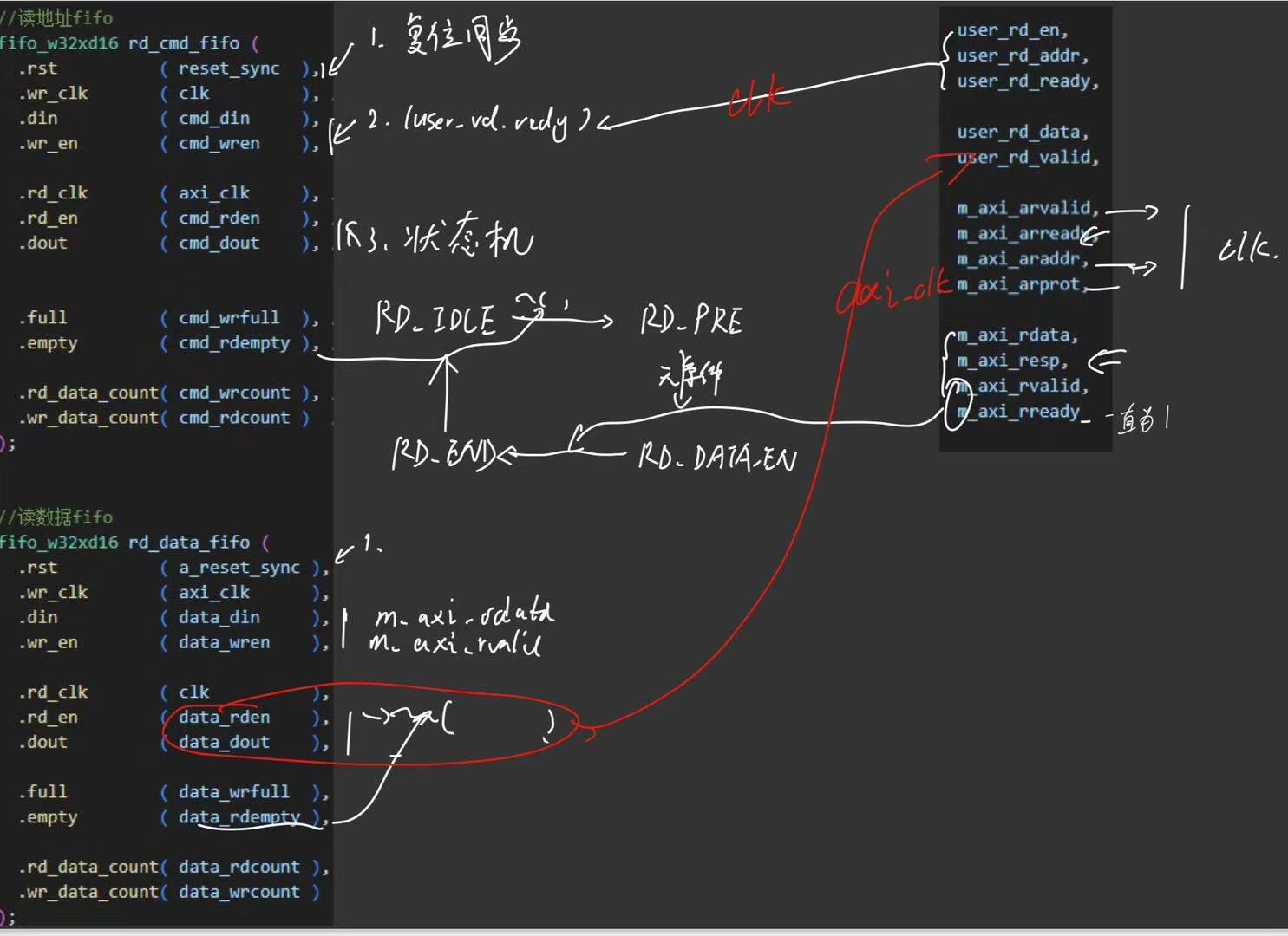
2.3 读通道
读通道的实现分两步,用户端发出读请求并给读的地址,然后从机根据地址发出数据,用户读出。
因此读地址fifo的逻辑部分与写通道一致,只有状态机跳转的RD_DATA_EN的条件根据模块端口有所改变,但是读数据fifo,是在AXI_CLK的时钟域下,端口输入有效及端口输入数据,根据非空开始用户读,然后赋给模块用户端口
`timescale 1ns / 1ps
//
// Description: AXI_LITE读通道
//
module axilite_rd_channel#(
	parameter USER_RD_DATA_WIDTH    = 32 , //用户读数据位宽和AXI4—Lite数据位宽保持一致
	parameter AXI_DATA_WIDTH 		= 32,
	parameter AXI_ADDR_WIDTH        = 32
)(
	input   wire								    clk,
	input   wire								    axi_clk,
	input   wire								    reset,

    //用户端读请求,读地址信号
	input   wire								    user_rd_en,
	input   wire  [AXI_ADDR_WIDTH-1 :0]		        user_rd_addr,
	output  wire                                    user_rd_ready,

	output  reg   [USER_RD_DATA_WIDTH-1:0]	        user_rd_data,
	output  reg                                     user_rd_valid,
    //与AXI_LITE从机 交互信号
	output  reg   		 							m_axi_arvalid, // axi read address channel
	input   wire   		 							m_axi_arready,
	output  reg   [AXI_ADDR_WIDTH-1:0] 				m_axi_araddr,
	output  wire  [2:0] 							m_axi_arprot,

	input   wire  [AXI_DATA_WIDTH-1:0]	    		m_axi_rdata,   // axi read data channel
	input   wire  [1:0] 				    		m_axi_resp,
	input   wire     					    		m_axi_rvalid,
	output  wire   						   	 		m_axi_rready
);

(* dont_touch = "true"*) reg reset_sync_d0;  //user clk
(* dont_touch = "true"*) reg reset_sync_d1;
(* dont_touch = "true"*) reg reset_sync;
(* dont_touch = "true"*) reg a_reset_sync_d0; //axi clk
(* dont_touch = "true"*) reg a_reset_sync_d1;
(* dont_touch = "true"*) reg a_reset_sync;

reg	 [31:0]  cmd_din;
reg          cmd_wren;
wire [31:0]  cmd_dout;
reg 		 cmd_rden;
wire		 cmd_wrfull;
wire		 cmd_rdempty;
wire [4:0]   cmd_wrcount;
wire [4:0]   cmd_rdcount;

reg	 [31:0]  data_din;
reg          data_wren;
wire [31:0]  data_dout;
wire 		 data_rden;
wire		 data_wrfull;
wire		 data_rdempty;
wire [4:0]   data_wrcount;
wire [4:0]   data_rdcount;


reg [2 : 0]	 cur_status;
reg [2 : 0]	 nxt_status;

localparam RD_IDLE     = 3'b000;
localparam RD_PRE      = 3'b001;
localparam RD_DATA_EN  = 3'b010;
localparam RD_END      = 3'b100;
/*--------------------------------------------------*\
				     assign
\*--------------------------------------------------*/
assign user_rd_ready = reset_sync ? 1'b0 : cmd_wrcount <= 'd12 ;
assign m_axi_rready  = 1'b1;
assign m_axi_arprot  = 0;
/*--------------------------------------------------*\
				     CDC process
\*--------------------------------------------------*/
always @(posedge clk) begin
	reset_sync_d0   <= reset;
	reset_sync_d1   <= reset_sync_d0;
	reset_sync      <= reset_sync_d1;
end

always @(posedge axi_clk) begin
	a_reset_sync_d0 <= reset;
	a_reset_sync_d1 <= a_reset_sync_d0;
	a_reset_sync    <= a_reset_sync_d1;
end

/*--------------------------------------------------*\
               wirte addr to cmd fifo
\*--------------------------------------------------*/
always @(posedge clk) begin
	if (user_rd_ready) begin
		cmd_wren  <= user_rd_en;
		cmd_din   <= user_rd_addr;
	end
	else begin
		cmd_wren  <= 0;
		cmd_din   <= 0;
	end
end

/*--------------------------------------------------*\
	            RD state machine
\*--------------------------------------------------*/
always @(posedge axi_clk) begin
	if (a_reset_sync) begin
		cur_status <= RD_IDLE;
	end
	else begin
		cur_status <= nxt_status;
	end
end

always @(*) begin
	if (a_reset_sync) begin
		nxt_status <= RD_IDLE;
	end
	else begin
		case(cur_status)
			RD_IDLE : begin
 				if (~cmd_rdempty)
					nxt_status <= RD_PRE;
				else
					nxt_status <= cur_status;
			end
			RD_PRE : begin
				nxt_status <= RD_DATA_EN;
			end
			RD_DATA_EN : begin
				if (m_axi_rvalid && m_axi_rready)
					nxt_status <= RD_END;
				else
					nxt_status <= cur_status;
			end
			RD_END : begin
				nxt_status <= RD_IDLE;
			end
			default : nxt_status <= RD_IDLE;
		endcase
	end
end

/*-----------------------------------------------------------*\
                  read addr from cmd_fifo
\*-----------------------------------------------------------*/
always @(*) begin
	if (a_reset_sync)
		cmd_rden  <= 0;
	else
		cmd_rden  <= cur_status == RD_PRE;
end

always @(posedge axi_clk) begin
	if (cmd_rden)
		m_axi_araddr <= cmd_dout;
	else
		m_axi_araddr <= m_axi_araddr;
end

always @(posedge axi_clk) begin
	if (a_reset_sync)
		m_axi_arvalid <= 0;
	else if (cur_status == RD_PRE)
		m_axi_arvalid <= 1'b1;
	else if (m_axi_arvalid && m_axi_arready)
		m_axi_arvalid <= 0;
end

/*-----------------------------------------------------------*\
                  read user data from data fifo
\*-----------------------------------------------------------*/
always @(posedge axi_clk) begin
	data_din  <= m_axi_rdata;
	data_wren <= m_axi_rvalid;
end

assign data_rden = reset_sync ? 1'b0 : ~data_rdempty;

always @(posedge clk) begin
	user_rd_valid  <= data_rden;
	user_rd_data   <= data_dout;
end

//读地址fifo
fifo_w32xd16 rd_cmd_fifo (
  .rst          ( reset_sync  ), // input wire rst
  .wr_clk       ( clk         ), // input wire wr_clk         用户写时钟
  .din          ( cmd_din     ), // input wire [31 : 0] din
  .wr_en        ( cmd_wren    ), // input wire wr_en

  .rd_clk       ( axi_clk     ), // input wire rd_clk         从机读时钟
  .rd_en        ( cmd_rden    ), // input wire rd_en
  .dout         ( cmd_dout    ), // output wire [31 : 0] dout


  .full         ( cmd_wrfull  ), // output wire full
  .empty        ( cmd_rdempty ), // output wire empty

  .rd_data_count( cmd_wrcount ), // output wire [4 : 0] rd_data_count
  .wr_data_count( cmd_rdcount )  // output wire [4 : 0] wr_data_count
);


//读数据fifo
fifo_w32xd16 rd_data_fifo (
  .rst          ( a_reset_sync ), // input wire rst
  .wr_clk       ( axi_clk      ), // input wire wr_clk        从机写时钟
  .din          ( data_din     ), // input wire [31 : 0] din
  .wr_en        ( data_wren    ), // input wire wr_en

  .rd_clk       ( clk          ), // input wire rd_clk            用户读时钟
  .rd_en        ( data_rden    ), // input wire rd_en
  .dout         ( data_dout    ), // output wire [31 : 0] dout

  .full         ( data_wrfull  ), // output wire full
  .empty        ( data_rdempty ), // output wire empty

  .rd_data_count( data_rdcount ), // output wire [4 : 0] rd_data_count
  .wr_data_count( data_wrcount )  // output wire [4 : 0] wr_data_count
);
endmodule
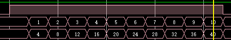
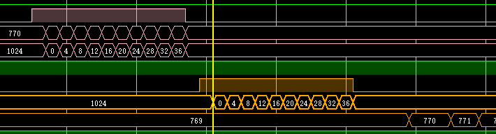
3.仿真
通过调用AXI_LITE接口的BRAM IP核,实/复位结束等一会儿进入写数据状态,读写数据(写10个数据,读10个数据),数据一致累加,地址也不断累加,地址最大为1024。
仿真结果如下,可以看出读写地址和数据完全一样,说明AXI_LITE接口代码实现无误。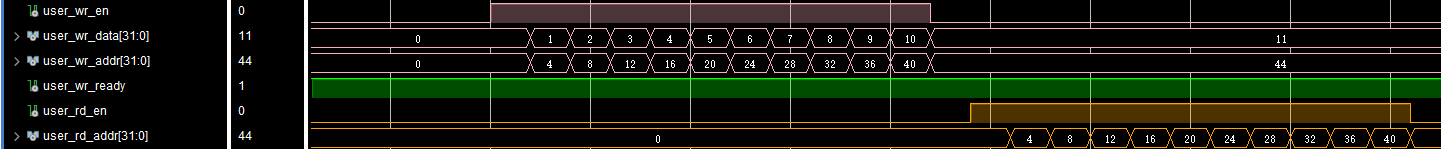
![]()

需要工程请私信