文章目录
- 前言
- 设计Excel模板
- Input/Output属性
- Sender/Receiver属性
- Matlab脚本
- 自动创建Input/Output接口
- 自动创建RTE Sender/Receiver port
- 实现效果
- Excel设置
- 运行新建Input与Output
- 运行创建RTE Port及Mapping
- 总结
前言
在之前的一篇文章中,介绍了Autosar Parameter Port的创建与mapping。基于此思路,本文介绍Autosar RTE中的Sender/Receiver接口在Simulink中的自动创建,及与对应的Simulink Output/Input接口的mapping.我们这里仍采用Excel来管理Interface。
设计Excel模板
在开始编写脚本以前,需要设计可行的Excel模板,好的模板格式可以节省部分代码的工作量。
Input/Output属性
首先我们需要在Simulink中创建需要mapping的Input及Output,那我们需要提取出Input/Output接口中的关键信息,Interface名称,数据类型,维度是非常重要的。

在本脚本中只设置了这三个属性,最大最小值,单位等不是很重要,列在Excel中只是为了方便查看。
Sender/Receiver属性
在进行Input/Output与RTE接口的mapping时,我们可以看到几个关键的信息,DataAccessMode-数据的访问模式(一般就用显式或隐式),Port,Element

我们设计Excel如下:

Description不用来作为脚本输入,只是为了描述接口。
Matlab脚本
自动创建Input/Output接口
在创建Input/Output接口之前,需要有一个Autosar的Simulink模型,此处我们通过脚本创建一个Simulink模型,再通过脚本配置模型配置,以达到Autosar的Simulink模型。
clc;
clear;
Excel_Name = 'RTEPort';
Model_Name = 'RTEInterface';
configRef = GenCodeCfg;

modeexist = exist (Model_Name);
if modeexist ~= 2 && modeexist ~= 4
new_system(Model_Name,'model');
attachConfigSet(Model_Name,configRef);
setActiveConfigSet(Model_Name,'RteCfg');
save_system(Model_Name);
end
GenCodeCfg是我从别的项目中导出的模型配置,其实对于Autosar的Simulink模型来说,主要配置SystemTargetFile为autosar.tlc,再将SolverType设置为Fixed-step即可使用Autosar SWC Component功能(在模型中使用Crtl + Shift + C也可以打开此功能,进行mapping)
通过new_system创建模型,通过save_system保存模型。使用exist只是为了验证模型是否已经被创建,否则new_system会报错,也可以通过在模型名中加入时间戳来避免此问题。
在创建Input/Output前,先删除模型中的端口,如下代码所示
open_system(Model_Name);
BlockPaths = find_system(Model_Name,'Type','Block')
for i=1:length(BlockPaths)
    delete_block(BlockPaths(i));
end
读取Excel中的信息,以创建端口
思路:
1.通过xlsread读取excel中的信息
2.通过add_block添加Input模块及对应的属性
3.将新建的模块位置进行排列整齐
具体代码如下所示:
RTEcolumn = {'ModeInterface','DataType','Dimensions',...
    'MinVal','MaxVal','Unit','RTEDataAccessMode','RTEPortName','RTEDataElement','Description'};
[~,Sheet_Cell] = xlsfinfo(Excel_Name)

for sheet_num = 1:length(Sheet_Cell) %遍历当前Excel中的Sheet页
    if strcmpi(Sheet_Cell{sheet_num},'RTEInput')%找到RTEInput表
        [~,~,RTEInput_Parameter]  = xlsread(Excel_Name,Sheet_Cell{sheet_num})%获取RTEInput中的信息
        RTEInput_Parametercolumn_num = size(RTEInput_Parameter,2);%获取列数
        RTEInput_Parameterrow_num = size(RTEInput_Parameter,1);%获取行数
        %获取参数在表中的列数
        for j = 1:RTEInput_Parametercolumn_num
            for jj = 1:length(RTEcolumn)
                if strcmpi(RTEInput_Parameter{1,j},RTEcolumn{jj})
                    RTEInput_Parameter_column_num(j) = jj;%Parameter所在列
                    break;
                else
                    RTEInput_Parameter_column_num(j) = 0;
                end

            end
        end
        for ii = 1:RTEInput_Parametercolumn_num%找不到对应列名称时报错
            if RTEInput_Parameter_column_num(ii) == 0
                    error('not find Parametercolumn:%s',RTEcolumn{ii});
            end
        end
        for j=2:RTEInput_Parameterrow_num
            RTEInput_ParameterName = strcat(Model_Name,'/',RTEInput_Parameter{j,RTEInput_Parameter_column_num(1)});
            handle = add_block('simulink/Sources/In1',RTEInput_ParameterName,'OutDataTypeStr',RTEInput_Parameter{j,RTEInput_Parameter_column_num(2)},...
                'PortDimensions',num2str(RTEInput_Parameter{j,RTEInput_Parameter_column_num(3)}));
           % set_param(handle,name,Parameter{Parameter_column_num,j});
        end
        % 找出外部输入端口
        Output_handles = find_system(Model_Name,'FindAll','on','SearchDepth','1','BlockType','Inport');
        port_pos=get(Output_handles(1),'Position');
        for i=2:length(Output_handles)
            new_pos(1)=port_pos(1);
            new_pos(3)=port_pos(3);
            new_pos(2)=port_pos(2)+15 * i;
            new_pos(4)=port_pos(4)+15 * i;
            set_param(Output_handles(i),'Position',new_pos);
        end

    end

end
save_system(Model_Name);
输出端口与输入端口类似,此处不再叙述。
自动创建RTE Sender/Receiver port
跟之前创建Paramter Port类似,只是替换了下API函数
在创建Port前,先删除模型中原有的Port
hModel= Model_Name;
arProps = autosar.api.getAUTOSARProperties(hModel)
slMap = autosar.api.getSimulinkMapping(hModel);
% addPackageableElement(arProps,'ParameterInterface','/Interface','ParameterPort',...
%   'IsService',false);%创建Interface
%删除Receiverport
arPortType = 'DataReceiverPort';
aswcPath = find(arProps,[],'AtomicComponent','PathType','FullyQualified');
rPorts=find(arProps,aswcPath{1},arPortType,'PathType','FullyQualified')
 for ii=1:length(rPorts)
     delete(arProps,rPorts{ii})
 end
 %删除Senderport
arPortType = 'DataSenderPort';
aswcPath = find(arProps,[],'AtomicComponent','PathType','FullyQualified');
sPorts=find(arProps,aswcPath{1},arPortType,'PathType','FullyQualified')
 for ii=1:length(sPorts)
     delete(arProps,sPorts{ii})
 end
%删除Interface
ifPaths = find(arProps,[],'SenderReceiverInterface','PathType','FullyQualified')
for ii=1:length(ifPaths)
    delete(arProps,ifPaths{ii})
end
通过Excel读到的值创建Interface和DataElement,然后对Input和Receiver Port进行mapping
 for ii=2:RTEInput_Parameterrow_num
     RTEName = RTEInput_Parameter{ii,RTEInput_Parameter_column_num(1)};
     RTEPort =  RTEInput_Parameter{ii,RTEInput_Parameter_column_num(8)};
     DataElement = RTEInput_Parameter{ii,RTEInput_Parameter_column_num(9)};
     RTEDataAccessMode =  RTEInput_Parameter{ii,RTEInput_Parameter_column_num(7)};
     addPackageableElement(arProps,'SenderReceiverInterface','/Interface',RTEPort,...
    'IsService',false);
    add(arProps,RTEPort,'DataElements',DataElement);%创建dataElement
    add(arProps,aswcPath{1},'ReceiverPorts',RTEPort,'Interface',RTEPort);%创建port
    %mapping Inport
    mapInport(slMap,RTEName,RTEPort,DataElement,RTEDataAccessMode)

 end
实现效果
Excel设置


运行新建Input与Output
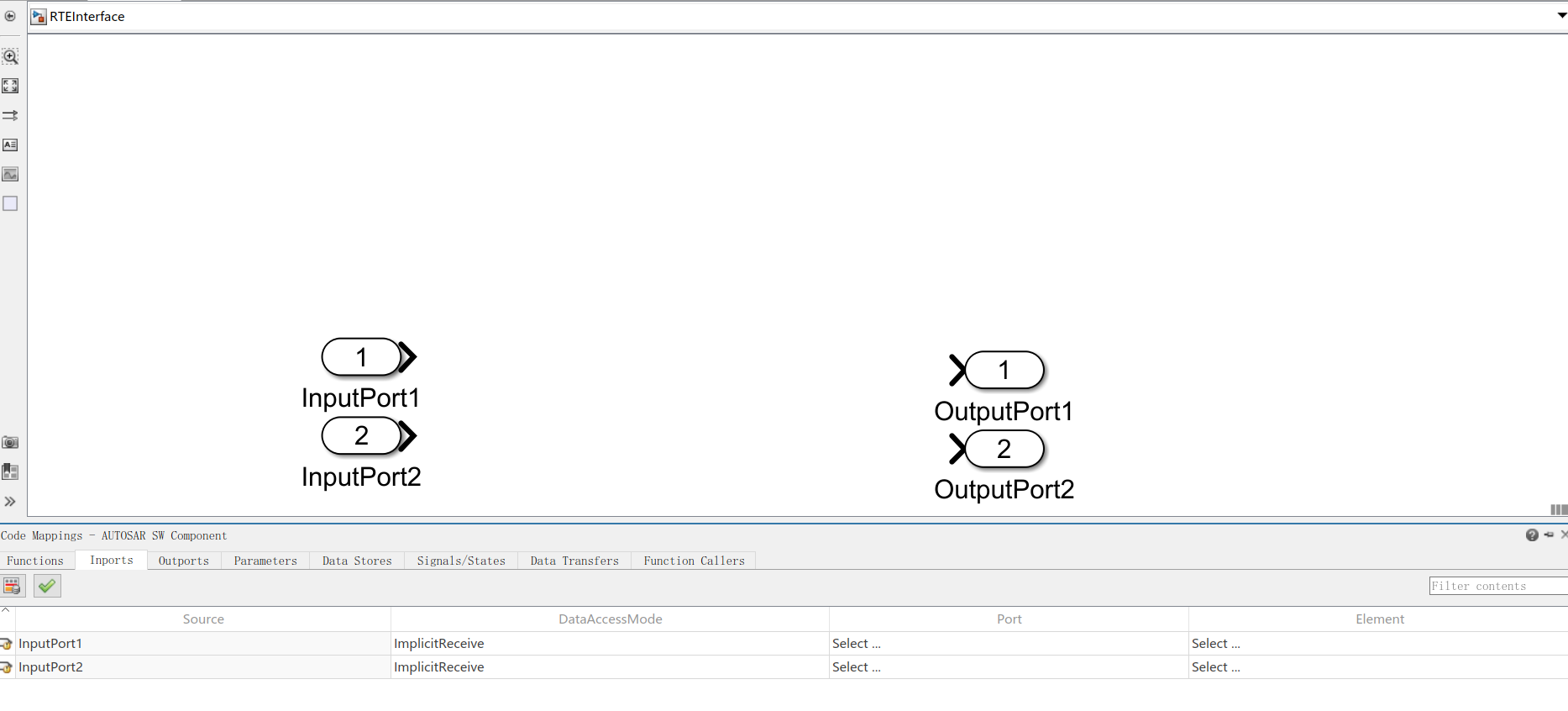
此时,还未创建RTE Port
运行创建RTE Port及Mapping
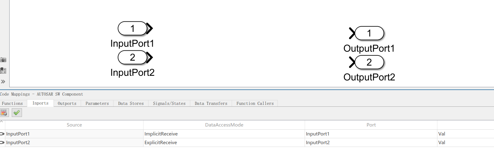

此时,Autosar RTE Sender/Receiver已自动创建,并成功mapping到了对应的Output/Input中
通过这种方式,可以在Excel管理RTE的接口,节省了手动建立Port及Mapping的时间。而且对于数据的访问方式(Implicit or Explicit),也可以很方便的修改
总结
工具或脚本只是为了提高工作效率,在工作中,还是需要有清晰的思路。遇到问题,需要有自己的方法论来解决问题。对于matlab和simulink来说,内置了很多api函数来帮助我们提高开发的效率,多多查看help是一个非常不错的选择。