原始笔记链接: https://mp.weixin.qq.com/s?__biz=Mzg4MjgxMjgyMg==&mid=2247486779&idx=1&sn=c75171844595150abc48d2dd59e7255f&chksm=cf51bfc2f82636d4e3f9c8526d0f25df1bea5496d9945d1e963961fea8c8fd630e7670b99afb#rd
↑ \uparrow ↑ 打开上述链接即可阅读全文
TRS 2023 | Spurs in Millimeter-Wave FMCW Radar System-on-Chip
毫米波雷达论文阅读: TRS 2023 | Spurs in Millimeter-Wave FMCW Radar System-on-Chip
论文链接:https://ieeexplore.ieee.org/document/10097751
0 Abstract
-
研究内容
-
present a nonlinear system model to evaluate the impact of circuit nonlinearities on spurs in millimeter-wave FMCW radar system-on-chips
-
The developed model includes:
✅ Harmonics of the frequency multiplier (频率乘法器的谐波)
✅ Nonlinearity of the power amplifier (PA) and low-noise amplifier (LNA) (功率放大器和低噪声放大器的非线性度)
✅ Switching operation of the receiver (RX) mixer (接收机混频器的切换操作)
✅ Limited bandwidth of the PA, LNA, transmitter (TX) and RX antennas (PA, LNA, 发射接收天线的有效带宽)
✅ TX-to-RX leakage (发射接收泄漏)
-
-
意义
- The nonlinear model can be used to derive frequency and amplitude of spurs in the radar IF spectrum
- without time-consuming simulations
-
Insights : The major insights about the impact of different nonlinearities and their interactions
- Harmonics of the frequency multiplier appear as spurs in the IF spectrum
- PA can be driven in its nonlinear region to mitigate the harmonics generated by the frequency multiplier
- Bandwidth of the TX and RX systems should be limited to attenuate the undesired harmonics(衰减不希望出现的谐波)
- Interaction between the TX-to-RX leakage signal and the LNA nonlinearity can lead to spurs close to the target echo in the IF spectrum
1 Introduction
-
背景: Millimeter-wave high-resolution radars的重要性
- Automotive sensors (ADAS, autonomous driving)
- Medical imaging, vital signs monitoring, gesture recognition
- IoT sensors, smart buildings, industrial transport, robotics
-
背景: mm-wave radar SoC 的最新进展
- Implemented in CMOS, SOI, SiGe processes
- Operating at 60 GHz, 77 GHz, 76-81 GHz, 140 GHz, 200-300 GHz
- Achieving high range resolution by using higher mm-wave bands and wide bandwidth
- Achieving high angular resolution using MIMO architecture
-
问题:广泛使用的FMCW雷达系统存在Spurs
-
Signal generation can be challenging due to requirements on:
✅ Bandwidth
✅ Phase noise
✅ Jitter
✅ Spurs
-
前三种已经有解决方案:Nonlinear effects such as chirp nonlinearity can be mitigated using error correction or calibration techniques
-
Spurs: Spurs are undesired signals in the radar IF spectrum that can be generated by
❗ Harmonics of the frequency multiplier (因为low harmonic rejection ration(HRR) of the frequency multiplier)
❗ Nonlinearities of the power amplifier (PA) and low-noise amplifier (LNA) (通过 affect the harmonics level)
❗ TX-to-RX leakage (通过 affect the harmonics level)
-
结论:一个全面的非线性模型对于推导 对 FMCW雷达电路组件的有效电路和系统设计 的要求 至关重要
-
-
This paper : presents a nonlinear system model for mm-wave FMCW radars
-
includes several important effects
✅ harmonics of the frequency multiplier
✅ nonlinearity of the PA, LNA
✅ the switching operation of the RX mixer
✅ the limited bandwidth of the TX and RX
✅ the stop-band rejections of the TX, RX, and IF filter
✅ the TX-to-RX leakage
-
To evaluate circuit nonlinearities and their interactions
-
作用:
✅ The developed model can be used to estimate the frequency and amplitude of spurs in the radar IF spectrum
✅ without the need for time-consuming system and circuit simulations
-
2 Non-Linear System Model of FMCW Radar
2.1 Principles of FMCW Radar
-
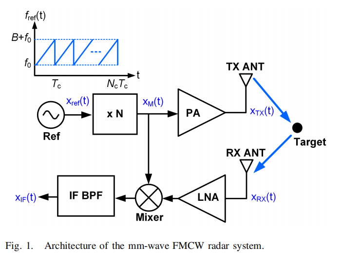
Architecture of a mm-wave FMCW radar system:
-
Reference chirp signal is generated at lower frequency (e.g. 10 GHz)
-
Then Frequency multiplier transforms it to mm-wave band
✅ 好处 :useful to achieve lower phase noise in the reference signal
-
Multiplier output signal is amplified by PA (功率放大器) and transmitted
-
Echo signal is received, amplified by LNA (低噪声放大器) and mixed with replica of multiplier output
-
Mixer output signal passes through IF bandpass filter (BPF)
-
-
Reference chirp signal
-
Linear time-dependent frequency:
✅ f r e f ( t ) = f 0 + S t 0 ≤ t ≤ T c f_{\mathrm{ref}}(t)=f_0+S t \quad 0 \leq t \leq T_c fref(t)=f0+St0≤t≤Tc
✅ T c T_c Tc: chirp period
-
Instantaneous phase:
✅ Φ r e f ( t ) = 2 π ∫ f r e f ( t ) d t = Φ 0 + 2 π f 0 t + π S t 2 \Phi_{\mathrm{ref}}(t)=2 \pi \int f_{\mathrm{ref}}(t) d t=\Phi_0+2 \pi f_0 t+\pi S t^2 Φref(t)=2π∫fref(t)dt=Φ0+2πf0t+πSt2
-
-
Frequency multiplier ideally generates
- Chirp signal with frequency N f r e f ( t ) Nf_{ref}(t) Nfref(t)
- Bandwidth of N B NB NB
- Slope of N S NS NS
- Period of T c T_c Tc
-
Received signal related to transmitted signal
- x R X ( t ) = G R x T X ( t − τ R ) x_{\mathrm{RX}}(t)=G_R x_{\mathrm{TX}}\left(t-\tau_R\right) xRX(t)=GRxTX(t−τR),
- GR: attenuation factor – G R = ( G A , T X G A , R X L s y s σ λ 2 ( 4 π ) 3 R 4 ) 1 2 G_R=\left(\frac{G_{\mathrm{A}, \mathrm{TX}} G_{\mathrm{A}, \mathrm{RX}} L_{\mathrm{sys}} \sigma \lambda^2}{(4 \pi)^3 R^4}\right)^{\frac{1}{2}} GR=((4π)3R4GA,TXGA,RXLsysσλ2)21
- τ R \tau_R τR: time-of-flight – τ R 0 = 2 R 0 c \tau_{R_0}=\frac{2 R_0}{c} τR0=c2R0
-
Mixer + BPF output signal
-
instantaneous phase: Φ I F ( t ) = N Φ r e f ( t ) − N Φ r e f ( t − τ R ( t ) ) \Phi_{\mathrm{IF}}(t)=N \Phi_{\mathrm{ref}}(t)-N \Phi_{\mathrm{ref}}\left(t-\tau_R(t)\right) ΦIF(t)=NΦref(t)−NΦref(t−τR(t))
-
⇒ \Rightarrow ⇒ 大致表示一个正弦信号, frequency:
✅ f I F = ( N S ) τ R 0 + f D = ( 2 N S c ) R 0 + ( 2 N f 0 c ) v f_{\mathrm{IF}}=(N S) \tau_{R_0}+f_D=\left(\frac{2 N S}{c}\right) R_0+\left(\frac{2 N f_0}{c}\right) v fIF=(NS)τR0+fD=(c2NS)R0+(c2Nf0)v
-
2D FFT to get Range and Velocity
-
2.2 FMCW Radar Nonlinear Model
A nonlinear system model which properly captures the circuit nonlinearities and interactions of different nonlinear effects with each other can be very valuable for efficient design of a mm-wave FMCW radar SoC.
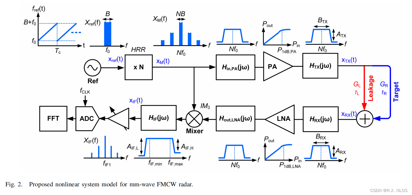
2.2.1 Important nonlinear effects in FMCW radar system model:
-
Output harmonics of frequency multiplier
-
Neglect spurs from reference circuits like PLL or DDS
-
Harmonics level depends on:
✅ Multiplier circuit structure
✅ Frequency band
✅ Chirp bandwidth
✅ Quality factor of passive components
✅ IC process features
-
The output of the frequency multiplier
✅ x o u t , M U L ( t ) = ∑ k = 1 ∞ a k cos [ k Φ r e f ( t ) ] x_{\mathrm{out}, \mathrm{MUL}}(t)=\sum_{k=1}^{\infty} a_k \cos \left[k \Phi_{\mathrm{ref}}(t)\right] xout,MUL(t)=∑k=1∞akcos[kΦref(t)]
-
-
Nonlinearity of PA
- Can change harmonics’ relative amplitude
- Especially at low supply voltages
-
Bandwidth of PA and TX
-
Bandwidth of PA: how output harmonics of the frequency multiplier reach to the TX antenna
✅ 受负载阻抗(用来最大化输出功率/efficiency)的限制
-
Bandwidth of Tx
✅ three possible scenarios:
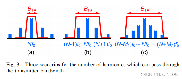
✅ 本文:假设为情况(b)
-
谐波 k k k的相对衰减系数:
✅ A T X , k = ∣ H T X ( j k ω 0 ) ∣ ∣ H T X ( j N ω 0 ) ∣ A_{\mathrm{TX}, \mathrm{k}}=\frac{\left|H_{\mathrm{TX}}\left(j k \omega_0\right)\right|}{\left|H_{\mathrm{TX}}\left(j N \omega_0\right)\right|} ATX,k=∣HTX(jNω0)∣∣HTX(jkω0)∣,
✅ 决定因素:信号分量之间的频率差、PA电路中使用的片上无源元件的质量因子,以及TX天线带宽。
-
-
TX-to-RX leakage signal
-
产生原因 :天线之间的耦合 + 芯片基板的耦合
-
后果 :desensitizes the RX circuits (特别是LNA) ⇒ \Rightarrow ⇒ 掩盖目标
-
解决 :目前的leakage cancellation已经可以做到 30~50dB
✅ still limits system performance
-
The received signal: x R X ( t ) = G R x T X ( t − τ R ) + G L x T X ( t − τ L ) x_{\mathrm{RX}}(t)=G_R x_{\mathrm{TX}}\left(t-\tau_R\right)+G_L x_{\mathrm{TX}}\left(t-\tau_L\right) xRX(t)=GRxTX(t−τR)+GLxTX(t−τL),
✅ leakage的后果can be different for short and long target ranges
-
-
Bandwidth of LNA and RX
-
意义:决定了能够到达混频器的谐波信号
-
LNA bandwidth:
✅ modeld by two transfer functions – H in, LNA ( j ω ) H_{\text {in, LNA }}(j \omega) Hin, LNA (jω) and H out,LNA ( j ω ) H_{\text {out,LNA }}(j \omega) Hout,LNA (jω)
✅ 分别对应 输入和输出匹配网络的 frequency responses
✅ 带宽限制因素: input matching network (负责提供optimum noise matching)
-
RX bandwidth:
✅ 仍使用上图(b) (the same as for the TX)
-
The relative attenuation of the harmonic k k k:
✅ A R X , k = ∣ H R X ( j k ω 0 ) ∣ ∣ H R X ( j N ω 0 ) ∣ A_{\mathrm{RX}, \mathrm{k}}=\frac{\left|H_{\mathrm{RX}}\left(j k \omega_0\right)\right|}{\left|H_{\mathrm{RX}}\left(j N \omega_0\right)\right|} ARX,k=∣HRX(jNω0)∣∣HRX(jkω0)∣.
-
-
Switching operation of RX mixer
- Generates intermodulation distortion (互调失真, IMD)
- Mixes 参考信号和LNA输出中的不同谐波 ⇒ \Rightarrow ⇒ 在IF上生成spurs
-
Bandwidth and attenuation of IF filter
- 通带纹波 的影响
- Fig. 3(a)的情况: distort the chirp signal ⇒ \Rightarrow ⇒ undesired amplitude and phase modulations
2.2.2 Model Limitations
存在Limitations的原因
- 模型考虑了 Most important effects for accurate radar performance evaluation
- Higher order imperfections excluded for clarity
- Apply approximations to keep model simple yet insightful
Limitations
-
Frequency multiplier
- Can have large amplitude variations of fundamentals/harmonics across bandwidth
- 此时,不能用 constant HRR (harmonic rejection ratio) 进行描述
- 可使用 average/worst-case HRR
-
Largest harmonics of multiplier
- May not be adjacent harmonics N±1
- Attenuated by PA, LNA, TX/RX antennas
-
PA/LNA nonlinearity
- Can significantly change across bandwidth
- Frequency-dependent P 1 d B P_{1dB} P1dB makes analysis intractable
- 解决:Use average P1dB for accuracy
- 接下来的分析会假设 leakage does not saturate LNA
-
Reference signal spurs neglected
- 本文仅Focus on spurs generated by radar
- Reference信号中的Spurs: PLL spurs via mechanisms like quantization noise
3 Analysis of FMCW Radar System
利用FMCW雷达的非线性系统模型,研究以下信号的spectral contents:
- TX输出
- RX输入
- IF
3.1 Analysis of Transmitter
-
Frequency multiplier output signal
- x o u t , M U L ( t ) = a N [ cos ( N Φ ) + k r e f cos [ ( N ± 1 ) Φ ] ] x_{\mathrm{out}, \mathrm{MUL}}(t)=a_{\mathrm{N}}\left[\cos (N \Phi)+k_{\mathrm{ref}} \cos [(N \pm 1) \Phi]\right] xout,MUL(t)=aN[cos(NΦ)+krefcos[(N±1)Φ]],
- Desired harmonic N
- Two adjacent harmonics N±1
- k r e f k_{\mathrm{ref}} kref related to HRR of multiplier
-
PA nonlinearity model output signal:
- 3rd order polynomial: N Φ , 3 N Φ , ( N ± 1 ) Φ , ( N ± 2 ) Φ , ( N ± 3 ) Φ , ( 3 N ± 1 ) Φ , ( 3 N ± 2 ) Φ , ( 3 N ± 3 ) Φ N \Phi, 3 N \Phi,(N \pm 1) \Phi,(N \pm 2) \Phi,(N \pm 3) \Phi,(3 N \pm 1) \Phi,(3 N \pm 2) \Phi ,(3 N \pm 3) \Phi NΦ,3NΦ,(N±1)Φ,(N±2)Φ,(N±3)Φ,(3N±1)Φ,(3N±2)Φ,(3N±3)Φ,
- Generates spectral regrowth
- Output spectrum 3 times wider than input
-
TX
- bandwidth allows N and N±1 harmonics
- Relative attenuation of N±1: ATX
- 即 A T X , N ± 1 = A T X A_{\mathrm{TX}, \mathrm{N} \pm 1}=A_{\mathrm{TX}} ATX,N±1=ATX
- (严格来说,TX system是一个动态非线性系统;本文,简化为一个 frequency-independent nonlinear model followed by a linear band-limited frequency response)
-
TX output signal derived using PA model
- x T X ( t ) = a T X [ cos ( N Φ ) + k T X cos [ ( N ± 1 ) Φ ] ] x_{\mathrm{TX}}(t)=a_{\mathrm{TX}}\left[\cos (N \Phi)+k_{\mathrm{TX}} \cos [(N \pm 1) \Phi]\right] xTX(t)=aTX[cos(NΦ)+kTXcos[(N±1)Φ]],
- 其中: a T X = α 1 , P A A i n + 3 4 ( 1 + 6 k r e f 2 ) α 3 , P A A i n 3 a_{\mathrm{TX}}=\alpha_{1, \mathrm{PA}} A_{\mathrm{in}}+\frac{3}{4}\left(1+6 k_{\mathrm{ref}}^2\right) \alpha_{3, \mathrm{PA}} A_{\mathrm{in}}^3 aTX=α1,PAAin+43(1+6kref2)α3,PAAin3, k T X = ( α 1 , P A A i n + 9 4 ( 1 + k r e f 2 ) α 3 , P A A i n 3 α 1 , P A A i n + 3 4 ( 1 + 6 k r e f 2 ) α 3 , P A A i n 3 ) A T X k r e f k_{\mathrm{TX}}=\left(\frac{\alpha_{1, \mathrm{PA}} A_{\mathrm{in}}+\frac{9}{4}\left(1+k_{\mathrm{ref}}^2\right) \alpha_{3, \mathrm{PA}} A_{\mathrm{in}}^3}{\alpha_{1, \mathrm{PA}} A_{\mathrm{in}}+\frac{3}{4}\left(1+6 k_{\mathrm{ref}}^2\right) \alpha_{3, \mathrm{PA}} A_{\mathrm{in}}^3}\right) A_{\mathrm{TX}} k_{\mathrm{ref}} kTX=(α1,PAAin+43(1+6kref2)α3,PAAin3α1,PAAin+49(1+kref2)α3,PAAin3)ATXkref.
- Includes fundamental and harmonic components
- Harmonics level k T X < k r e f k_{TX} < k_{ref} kTX<kref ⇒ \Rightarrow ⇒ 意味着 TX输出时,谐波水平降低
- 即:在非线性区域驱动PA,以减轻频率乘法器产生的谐波 + 提高PA效率 是有益的。
-
Key insights:
-
PA nonlinearity decreases harmonics level
🚩 Beneficial to drive PA in nonlinear region
-
TX bandwidth should limit harmonics
🚩 Filter can further suppress harmonics
-
3.2 Analysis of Receiver
-
Received signal :
- Composed of target echo and TX-RX leakage
-
Without leakage signal :
-
LNA output signal derived using LNA nonlinearity model: x o u t , L N A ( t ) = a o u t , L N A [ cos [ N Φ ( t − τ R ) ] + k R X cos [ ( N ± 1 ) Φ ( t − τ R ) ] ] , \begin{aligned} & x_{\mathrm{out}, \mathrm{LNA}}(t) \\ & =a_{\mathrm{out}, \mathrm{LNA}}\left[\cos \left[N \Phi\left(t-\tau_R\right)\right]+k_{\mathrm{RX}} \cos \left[(N \pm 1) \Phi\left(t-\tau_R\right)\right]\right],\end{aligned} xout,LNA(t)=aout,LNA[cos[NΦ(t−τR)]+kRXcos[(N±1)Φ(t−τR)]],
-
IF signal
✅ x I F ( t ) = a I F [ cos [ N Ψ 1 ( t ) ] + k r e f k R X cos [ ( N ± 1 ) Ψ 1 ( t ) ] ] x_{\mathrm{IF}}(t)=a_{\mathrm{IF}}\left[\cos \left[N \Psi_1(t)\right]+k_{\mathrm{ref}} k_{\mathrm{RX}} \cos \left[(N \pm 1) \Psi_1(t)\right]\right] xIF(t)=aIF[cos[NΨ1(t)]+krefkRXcos[(N±1)Ψ1(t)]]✅ Ψ 1 ( t ) = Φ ( t ) − Φ ( t − τ R ) \Psi_1(t)=\Phi(t)-\Phi\left(t-\tau_R\right) Ψ1(t)=Φ(t)−Φ(t−τR)
🚩 结论1:
-
-
Key insights:
-
结论1:中频处的激励电平低于参考信号的原始谐波电平 (IF spurs level < reference harmonics level)
✅ k I F ≈ ( 1 − 3 β P i n , L N A P l d B , L N A 1 − β P i n , L N A P l d B , L N A ) ( 1 − 3 β P i n , P A P l d B , P A 1 − β P i n , P A P l d B , P A ) A R X A T X k r e f 2 k_{\mathrm{IF}} \approx\left(\frac{1-3 \beta \frac{P_{\mathrm{in}, \mathrm{LNA}}}{P_{\mathrm{ldB}, \mathrm{LNA}}}}{1-\beta \frac{P_{\mathrm{in}, \mathrm{LNA}}}{P_{\mathrm{ldB}, \mathrm{LNA}}}}\right)\left(\frac{1-3 \beta \frac{P_{\mathrm{in}, \mathrm{PA}}}{P_{\mathrm{ldB}, \mathrm{PA}}}}{1-\beta \frac{P_{\mathrm{in}, \mathrm{PA}}}{P_{\mathrm{ldB}, \mathrm{PA}}}}\right) A_{\mathrm{RX}} A_{\mathrm{TX}} k_{\mathrm{ref}}^2 kIF≈(1−βPldB,LNAPin,LNA1−3βPldB,LNAPin,LNA)(1−βPldB,PAPin,PA1−3βPldB,PAPin,PA)ARXATXkref2. -
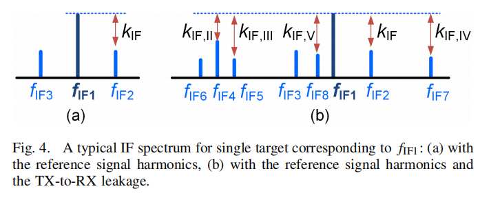
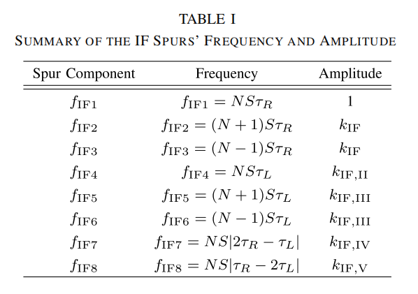
结论2:中频包含了三个频率分量: f I F 1 = N S τ R f_{\mathrm{IF} 1}=N S \tau_R fIF1=NSτR, f I F 2 = ( N + 1 ) S τ R f_{\mathrm{IF} 2}=(N+1) S \tau_R fIF2=(N+1)SτR, f I F 3 = ( N + 2 ) S τ R f_{\mathrm{IF} 3}=(N+2) S \tau_R fIF3=(N+2)SτR
✅ Spurs can cause overlap between IF spectra ⇒ \Rightarrow ⇒ 降低雷达距离分辨率
-
-
With leakage signal:
- 相当于LNA有两个输入: x in,LNA ( t ) = x echo ( t ) + x leak ( t ) x_{\text {in,LNA }}(t)=x_{\text {echo }}(t)+x_{\text {leak }}(t) xin,LNA (t)=xecho (t)+xleak (t),
- Leakage and LNA nonlinearity interaction generates extra spurs
- LNA output signal includes spectral components related to leakage: x o u t , L N A ( t ) G R a T X [ C 1 cos [ N Φ ( t − τ R ) ] + C 2 cos [ ( N ± 1 ) Φ ( t − τ R ) ] + C 3 cos [ N Φ ( t − τ L ) ] + C 4 cos [ ( N ± 1 ) Φ ( t − τ L ) ] + C 5 cos [ 2 N Φ ( t − τ R ) − N Φ ( t − τ L ) ] + C 6 cos [ N Φ ( t − τ R ) − 2 N Φ ( t − τ L ) ] ] , \begin{aligned} & x_{\mathrm{out}, \mathrm{LNA}}(t) \\ & \qquad G_R a_{\mathrm{TX}}\left[C_1 \cos \left[N \Phi\left(t-\tau_R\right)\right]\right. \\ & \quad+C_2 \cos \left[(N \pm 1) \Phi\left(t-\tau_R\right)\right] \\ & \quad+C_3 \cos \left[N \Phi\left(t-\tau_L\right)\right]+C_4 \cos \left[(N \pm 1) \Phi\left(t-\tau_L\right)\right] \\ & \quad+C_5 \cos \left[2 N \Phi\left(t-\tau_R\right)-N \Phi\left(t-\tau_L\right)\right] \\ & \left.\quad+C_6 \cos \left[N \Phi\left(t-\tau_R\right)-2 N \Phi\left(t-\tau_L\right)\right]\right],\end{aligned} xout,LNA(t)GRaTX[C1cos[NΦ(t−τR)]+C2cos[(N±1)Φ(t−τR)]+C3cos[NΦ(t−τL)]+C4cos[(N±1)Φ(t−τL)]+C5cos[2NΦ(t−τR)−NΦ(t−τL)]+C6cos[NΦ(t−τR)−2NΦ(t−τL)]],
- IF signal : x I F ( t ) ≈ a I F [ C 1 cos [ N Ψ 1 ( t ) ] + C 2 k r e f cos [ ( N ± 1 ) Ψ 1 ( t ) ] + C 3 cos [ N Ψ 2 ( t ) ] + C 4 k r e f cos [ ( N ± 1 ) Ψ 2 ( t ) ] + C 5 cos [ N Ψ 3 ( t ) ] + C 6 cos [ N Ψ 4 ( t ) ] ] \begin{aligned} x_{\mathrm{IF}}(t) \approx & a_{\mathrm{IF}}\left[C_1 \cos \left[N \Psi_1(t)\right]+C_2 k_{\mathrm{ref}} \cos \left[(N \pm 1) \Psi_1(t)\right]\right. \\ & +C_3 \cos \left[N \Psi_2(t)\right]+C_4 k_{\mathrm{ref}} \cos \left[(N \pm 1) \Psi_2(t)\right] \\ & \left.+C_5 \cos \left[N \Psi_3(t)\right]+C_6 \cos \left[N \Psi_4(t)\right]\right]\end{aligned} xIF(t)≈aIF[C1cos[NΨ1(t)]+C2krefcos[(N±1)Ψ1(t)]+C3cos[NΨ2(t)]+C4krefcos[(N±1)Ψ2(t)]+C5cos[NΨ3(t)]+C6cos[NΨ4(t)]]
-
The Spurs level in the IF:
-
k I F ≈ [ 1 + r 2 − β ( 3 + 2 r 2 ) P i n , L N A P 1 d B , L N A 1 + r 2 − β ( 1 + 2 r 2 ) P i n , L N A P 1 d B , L N A ] [ 1 − 3 β P i n , P A P d d B , P A 1 − β P i n , P A P 1 d B , P A ] × A R X A T X k r e f 2 . \begin{gathered}k_{\mathrm{IF}} \approx\left[\frac{1+r^2-\beta\left(3+2 r^2\right) \frac{P_{\mathrm{in}, \mathrm{LNA}}}{P_{1 \mathrm{~dB}, \mathrm{LNA}}}}{1+r^2-\beta\left(1+2 r^2\right) \frac{P_{\mathrm{in}, \mathrm{LNA}}}{P_{1 \mathrm{~dB}, \mathrm{LNA}}}}\right]\left[\frac{1-3 \beta \frac{P_{\mathrm{in}, \mathrm{PA}}}{P_{\mathrm{ddB}, \mathrm{PA}}}}{1-\beta \frac{P_{\mathrm{in}, \mathrm{PA}}}{P_{1 \mathrm{~dB}, \mathrm{PA}}}}\right] \\ \times A_{\mathrm{RX}} A_{\mathrm{TX}} k_{\mathrm{ref}}^2 .\end{gathered} kIF≈ 1+r2−β(1+2r2)P1 dB,LNAPin,LNA1+r2−β(3+2r2)P1 dB,LNAPin,LNA 1−βP1 dB,PAPin,PA1−3βPddB,PAPin,PA ×ARXATXkref2.
-
取决于:
✅ Reference harmonics
✅ Leakage signal power
✅ PA/LNA nonlinearity
✅ TX/RX bandwidth
✅ IF filter attenuation
-
当 PA和LNA工作在线性功率范围时 (即 P i n , P A ≪ P 1 d B , P A P_{\mathrm{in}, \mathrm{PA}} \ll P_{1 \mathrm{~dB}, \mathrm{PA}} Pin,PA≪P1 dB,PA and P i n , L N A ≪ P 1 d B , L N A P_{\mathrm{in}, \mathrm{LNA}} \ll P_{1 \mathrm{~dB}, \mathrm{LNA}} Pin,LNA≪P1 dB,LNA):
✅ k I F ≈ A R X A T X k r e f 2 k_{\mathrm{IF}} \approx A_{\mathrm{RX}} A_{\mathrm{TX}} k_{\mathrm{ref}}^2 kIF≈ARXATXkref2.
🚩 ⇒ \Rightarrow ⇒ PA和LNA的非线性有利于降低谐波 (因为上式中的前两项总是小于1)
-
-
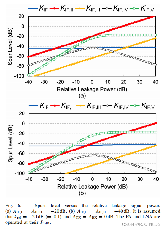
Leakage signal
-
Introduces new undesired components
-
如下图Fig 6所示
-
该理论能够指导:当给定相对泄露功率时,所需要的IF BPF阻带衰减
✅ A I F , L / H A_{IF,L/H} AIF,L/H 需使得 k I F , I I < k I F k_{\mathrm{IF}, \mathrm{II}}<k_{\mathrm{IF}} kIF,II<kIF & k I F , I V < k I F k_{\mathrm{IF}, \mathrm{IV}}<k_{\mathrm{IF}} kIF,IV<kIF
-
3.3 Radar Dynamic Range
-
Radar dynamic range (DR) :
-
D R n o i s e DR_{noise} DRnoise : Difference between RX signal power and noise floor
-
D R s p u r DR_{spur} DRspur (DR = D R s p u r DR_{spur} DRspur, 如果spur功率高于噪声功率): Difference between signal power and maximum spur level
-
-
DR can be maximized by:
-
Limiting largest spur below noise floor
-
D R s p u r = D R n o i s e DR_{spur} = DR_{noise} DRspur=DRnoise
-
-
D R s p u r DR_{spur} DRspur can be derived as:
-
− 20 log 10 ( k I F , max ) = P R X , max + 174 − N F − 10 log 10 ( B n ) -20 \log _{10}\left(k_{\mathrm{IF}, \max }\right)=P_{\mathrm{RX}, \max }+174-N F-10 \log _{10}\left(B_n\right) −20log10(kIF,max)=PRX,max+174−NF−10log10(Bn),
-
P R X , m a x P_{RX,max} PRX,max: Maximum RX input power
-
N F NF NF: Noise figure
-
B n B_n Bn: Noise bandwidth
-
k I F , max k_{\mathrm{IF}, \max } kIF,max: Maximum spur level in IF
-
-
上述对DR的限制能够作为约束计算如下参数:
-
Frequency multiplier harmonics
-
TX-RX leakage power
-
PA/LNA nonlinearity
-
4 Simulations and Discussions
4.1 Simulation Setup
- 140 GHz chirp signal, 5 GHz bandwidth
- ×8 frequency multiplier (17.5G reference signal) with -20 dBc harmonics
- ADS and MATLAB used for TX/RX circuit modeling
- Target: at 10 m range
4.2 Radar IF Spectrum
-
Compared theory and simulations for various nonlinearities
-
Impact of circuit nonlinearities on radar IF spectrum
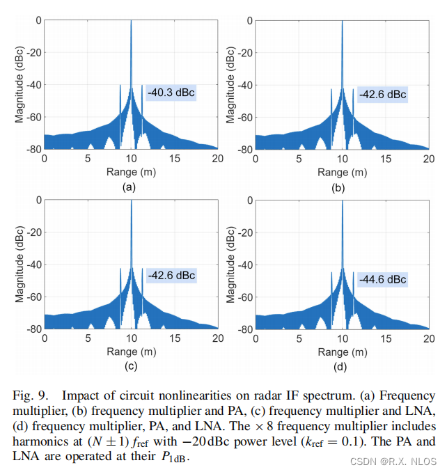
- Impact of leakage signal:
- ≤0.5 dB difference up to 0 dB leakage power
- Discrepancy increases to 2-3 dB at higher leakage
- Extra spur observed besides two harmonic spurs
- Amplitude matches theory
- Location depends on leakage delay
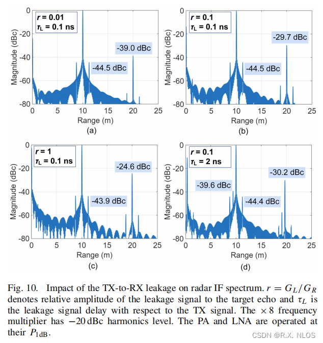
Developed model provides accurate results
4.3 Radar Range-Doppler Diagram
- Shows probability of false alarm due to spurs
- Reduced with PA/LNA nonlinearity
- Leakage signal spur increases false alarm
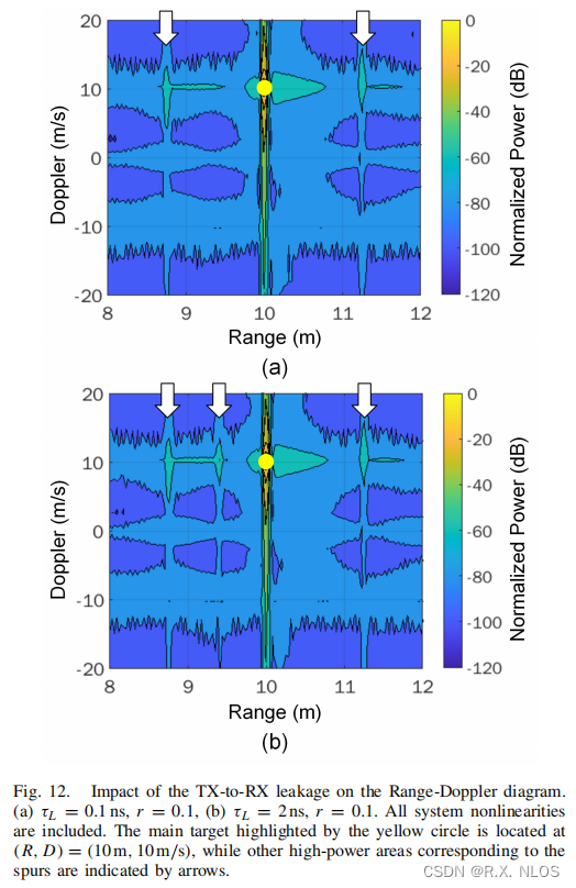
- Developed theory provides:
- Guidelines for IF filter attenuation
- Required harmonic/leakage/nonlinearity levels
5 Conclusion
- 本文为FMCW毫米波系统的分析提供了一个非线性模型
- 模型考虑了收发机的多个组件带来的影响
- 能够预测雷达IF中Spurs的频率和幅度,为电路设计提供参考