目录
前言:
调试准备工作:
修改内核默认打印等级
一、imx415驱动开发
1、硬件接线
2、设备树修改
2.1 创建 tegra234-p3767-camera-p3768-imx415-C-4lane.dtsi 文件
2.2 tegra234-p3767-camera-p3768-imx415-C-4lane.dtsi 添加到设备树
2.3 编译设备树
3、imx415驱动开发
3.1 imx415寄存器
1)mclk 时钟
2)lane数量
3)lane速率
4)分辨率
5)像素深度
6)Master/Slave模式
7)启流、停流相关
8)增益
编辑
9)曝光
编辑
10)All pixel模式 4lane 配置表
3.2 imx415驱动
1)Linux_for_Tegra/source/nvidia-oot/drivers/media/i2c/imx415_mode_tbls.h 源码
2)Linux_for_Tegra/source/nvidia-oot/include/media/imx415.h 源码
3)Linux_for_Tegra/source/nvidia-oot/drivers/media/i2c/nv_imx415.c 驱动文件
4)将 nv_imx415 添加到Makefile
二、编译调试
1、编译imx415驱动
2、安装 v4l-utils 并查看 /dev/video0信息
2.1 安装 v4l-utils
2.2 查看 /dev/video0 信息
3、抓拍
3.1 v4l2-ctl 命令验证vi抓拍
3.2 gstreamer英伟达命令抓拍
1)gst-launch-1.0 自动曝光、自动增益抓拍
2)gst-launch-1.0 设置曝光、增益抓拍
三、imx415驱动开发遇到的问题及解决方法
1、Jetson orin nano开发板的CAM0不支持4lane模式
2、使用 CSI0/1 时,需要将lane_polarity改为 6
3、v4l2-ctl 抓图命令报错
4、v4l2-ctl 抓图不成功,vi能收到数据,但数据不对
5、gstreamer抓图偏红色
四、曝光、增益、格式、焦距对拍照效果的影响
前言:
nvidia相机开发参考链接:相机软件开发解决方案 — NVIDIA Jetson Linux 开发者指南
可加载内核模块 (LKM)其实就是就是编译成ko模块。nvidia将所有模块都放在 nvidia-oot 目录下。参考链接:传感器软件驱动程序编程 — NVIDIA Jetson Linux 开发者指南
说明:博主使用野火的imx415摄像头模块,在 Jetson Orin Nano开发板上开发imx415驱动
调试准备工作:
修改内核默认打印等级
$ vi /etc/sysctl.conf
#
# /etc/sysctl.conf - Configuration file for setting system variables
# See /etc/sysctl.d/ for additional system variables.
# See sysctl.conf (5) for information.
#

#kernel.domainname = example.com

# Uncomment the following to stop low-level messages on console
kernel.printk = 8 8 8 8                #打印等级

###################################################################
# Functions previously found in netbase
#

# Uncomment the next two lines to enable Spoof protection (reverse-path filter)
# Turn on Source Address Verification in all interfaces to
# prevent some spoofing attacks
#net.ipv4.conf.default.rp_filter=1
#net.ipv4.conf.all.rp_filter=1

# Uncomment the next line to enable TCP/IP SYN cookies
# See http://lwn.net/Articles/277146/
一、imx415驱动开发
1、硬件接线
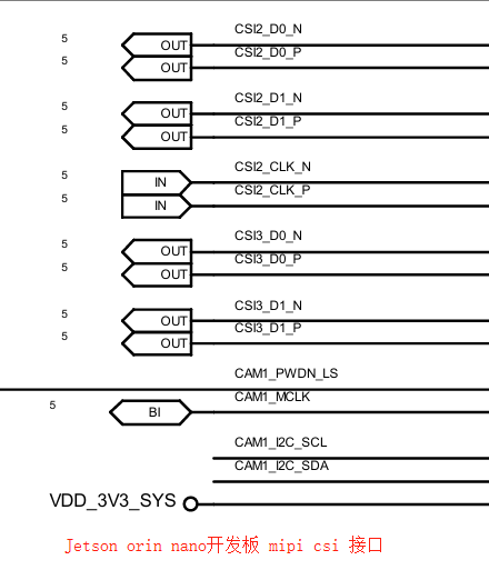
imx415模块和 Jetson orin nano开发板的csi接口中间有转接板。2 lane模式下,仅 CSI_D0 P/N 和 CSI_D1 P/N 有数据。我使用的是 4 lane 模式。
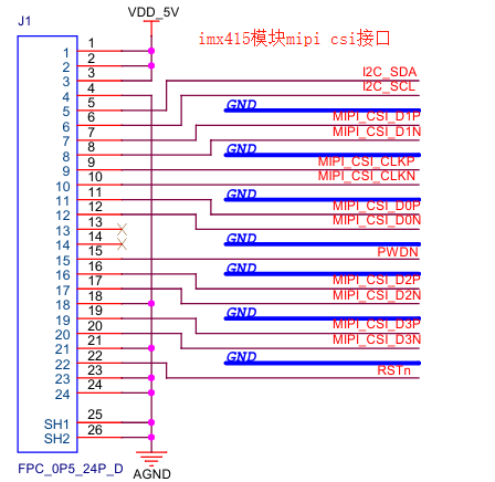
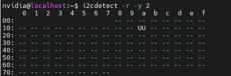
硬件接上后,用 i2cdetect 工具探测 I2C通不通。cam_i2cmux挂在i2c3下,因此命令如下:
$ i2cdetect -r -y 2
可以看到 imx415 的设备地址为 0x1a
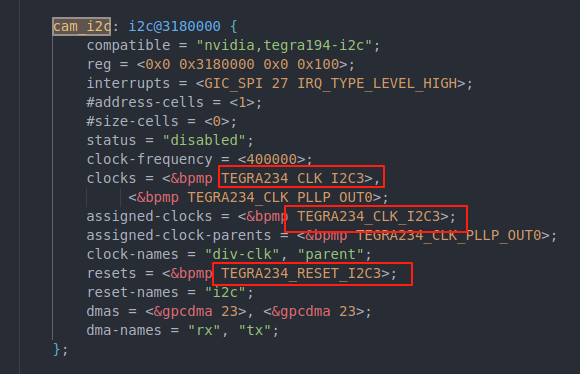
问题:如何知道 CAM1_I2C 挂在 i2c3下?
查看 Linux_for_Tegra/source/hardware/nvidia/t23x/nv-public/tegra234.dtsi
cam_i2c 为I2C3节点, 因此cam_i2cmux在I2C3节点下
2、设备树修改
设备树增加sensor参考文档:Sensor Software Driver Programming — NVIDIA Jetson Linux Developer Guide
2.1 创建 tegra234-p3767-camera-p3768-imx415-C-4lane.dtsi 文件
1)将 Linux_for_Tegra/source/hardware/nvidia/t23x/nv-public/overlay 目录下的 tegra234-p3767-camera-p3768-imx477-C.dts 作为模板拷贝一份 tegra234-p3767-camera-p3768-imx415-C-4lane.dtsi
imx415 模块 4 lane差分线接在CSI2上,CSI2对应"serial_c"(CSI0对应serial_a,依此类推),因此命名 "tegra234-p3767-camera-p3768-imx415-C-4lane.dtsi"
2)修改 tegra234-p3767-camera-p3768-imx415-C-4lane.dtsi
关键参数计算过程:
-
compatible = "ridgerun,imx415" 要和imx415驱动对应上
-
mclk_khz:imx415模块外接 37.125M晶振,因此 mclk_khz = "37125"
-
4 lane模式:因此 num_lanes = "4", bus-width = <4>;
-
CSI2:因此 tegra_sinterface = "serial_c",port-index = <2>
-
分辨率:根据 imx415分辨率设置 "active_w = 3864",active_h = "2192"
-
pixel_phase:像素格式,pixel_phase = "gbrg",调试时设置为 "rggb" 导致图像偏红色
-
csi_pixel_bit_depth:像素深度,imx415使用RAW12模式,因此 csi_pixel_bit_depth = "12"
-
pix_clk_hz:imx415 配置 lane频率为 891 Mbps,4lane,像素深度为12bit,pix_clk_hz = 891 Mbps × 4 / 12 = 297000000,我理解只要不小于此值即可。
-
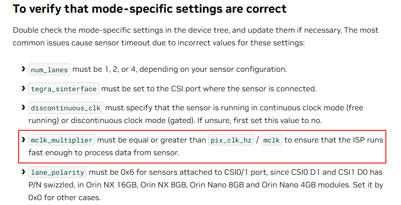
mclk_multiplier :mclk_multiplier ≥ pix_clk_hz / mclk = 297000000 / 37125000 = 8,因此mclk_multiplier = "8"。从nvidia官方手册可知,
mclk_multiplier必须大于等于pix_clk_hz / mclk,以确保ISP运行得足够快,能够处理来自传感器的数据。
-
增益,查看imx415手册
GAIN_PCG_0计算公式:GAIN_PCG_0 = Gain[dB] x 10 /3

GAIN_PCG_0 范围为 0 - 240d,因此 Gain范围为 0 - 72 [dB],我这里增益因子配置为 gain_factor = "10" ,Gain范围 0 - 72 [dB] 乘上增益因子,得到 min_gain_val = "0", max_gain_val = "720",step为 0.3dB 乘增益因子,因此 step_gain_val = "3"
-
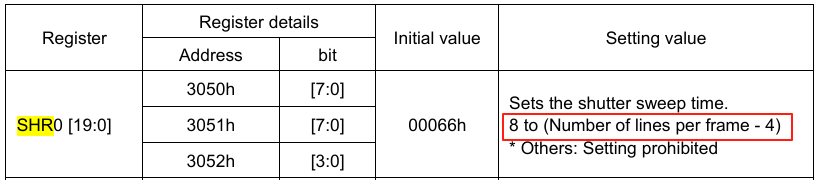
曝光:
曝光参数单位为us,需要根据帧率(30fps)、VMAX(2250)、 SHR0 值范围(8 到 Number oflines per frame - 4),按照下面公式倒推 exposure 最小值、最大值、step,我算得结果图下:
min_exp_time = "15";        /* 单位:us */
max_exp_time = "33214";     /* 单位:us */
step_exp_time = "15";       /* 单位:us */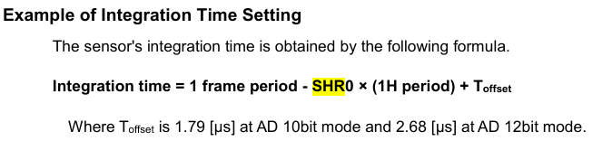
-
embedded_metadata_height:根据imx415手册来配置为 "1",如下图
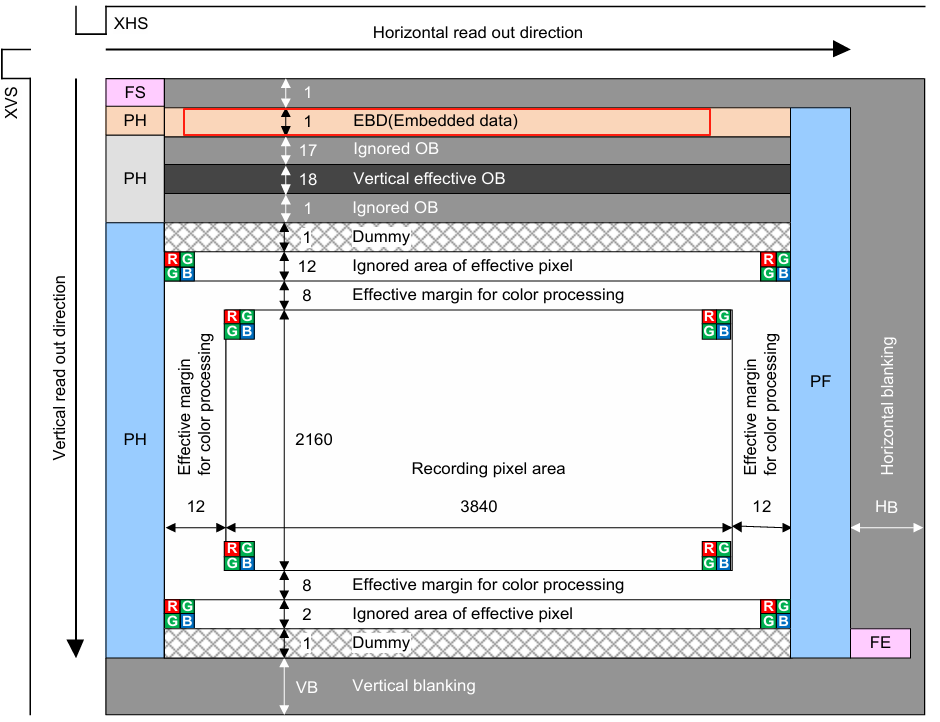
最终 tegra234-p3767-camera-p3768-imx415-C-4lane.dtsi 文件内容如下:
设备树描述了 VI(视频输入)、NvCSI 、传感器模块 的端口绑定关系
// SPDX-License-Identifier: GPL-2.0-only
// SPDX-FileCopyrightText: Copyright (c) 2023-2024, NVIDIA CORPORATION & AFFILIATES. All rights reserved.

///dts-v1/;
///plugin/;

#define CAM0_RST	TEGRA234_MAIN_GPIO(Q, 6)	/* add */
#define CAM0_PWDN	TEGRA234_MAIN_GPIO(H, 6)
#define CAM1_PWDN	TEGRA234_MAIN_GPIO(AC, 0)
#define CAM_I2C_MUX 	TEGRA234_AON_GPIO(CC, 3)

#include <dt-bindings/tegra234-p3767-0000-common.h>

/ {
	overlay-name = "Camera IMX415-C 4 lane";
	jetson-header-name = "Jetson 24pin CSI Connector";
	compatible = JETSON_COMPATIBLE_P3768;
	/*IMX415 connected on cam0 port */

	fragment@0 {
		target-path = "/";
		__overlay__ {
			tegra-capture-vi  {
				num-channels = <1>;
				ports {
					#address-cells = <1>;
					#size-cells = <0>;
					port@0 {
						reg = <0>;
						rbpcv3_imx415_vi_in1: endpoint {
							port-index = <2>;
							bus-width = <4>;
							remote-endpoint = <&rbpcv3_imx415_csi_out1>;
						};
					};
				};
			};
			tegra-camera-platform {
				compatible = "nvidia, tegra-camera-platform";
				/**
				* Physical settings to calculate max ISO BW
				*
				* num_csi_lanes = <>;
				* Total number of CSI lanes when all cameras are active
				*
				* max_lane_speed = <>;
				* Max lane speed in Kbit/s
				*
				* min_bits_per_pixel = <>;
				* Min bits per pixel
				*
				* vi_peak_byte_per_pixel = <>;
				* Max byte per pixel for the VI ISO case
				*
				* vi_bw_margin_pct = <>;
				* Vi bandwidth margin in percentage
				*
				* max_pixel_rate = <>;
				* Max pixel rate in Kpixel/s for the ISP ISO case
				*
				* isp_peak_byte_per_pixel = <>;
				* Max byte per pixel for the ISP ISO case
				*
				* isp_bw_margin_pct = <>;
				* Isp bandwidth margin in percentage
				*/
				num_csi_lanes = <4>;
				max_lane_speed = <1500000>;
				min_bits_per_pixel = <10>;
				vi_peak_byte_per_pixel = <2>;
				vi_bw_margin_pct = <25>;
				max_pixel_rate = <7500000>;
				isp_peak_byte_per_pixel = <5>;
				isp_bw_margin_pct = <25>;
				/**
				 * The general guideline for naming badge_info contains 3 parts, and is as follows,
				 * The first part is the camera_board_id for the module; if the module is in a FFD
				 * platform, then use the platform name for this part.
				 * The second part contains the position of the module, ex. "rear" or "front".
				 * The third part contains the last 6 characters of a part number which is found
				 * in the module's specsheet from the vendor.
				 */
				modules {
					module1 {
						badge = "jakku_rear_RBPCV3";
						position = "rear";
						orientation = "1";
						drivernode0 {
							pcl_id = "v4l2_sensor";
							sysfs-device-tree = "/sys/firmware/devicetree/base/bus@0/cam_i2cmux/i2c@1/rbpcv3_imx415_c@1a";
						};
					};
				};
			};
			bus@0 {
				host1x@13e00000 {
					nvcsi@15a00000 {
						num-channels = <1>;
						#address-cells = <1>;
						#size-cells = <0>;
						channel@0 {
							reg = <0>;
							ports {
								#address-cells = <1>;
								#size-cells = <0>;
								port@0 {
									reg = <0>;
									rbpcv3_imx415_csi_in1: endpoint@0 {
										port-index = <2>;
										bus-width = <4>;
										remote-endpoint = <&rbpcv3_imx415_out1>;
									};
								};
								port@1 {
									reg = <1>;
									rbpcv3_imx415_csi_out1: endpoint@1 {
										remote-endpoint = <&rbpcv3_imx415_vi_in1>;
									};
								};
							};
						};
					};
				};
				cam_i2cmux {
					status = "okay";
					compatible = "i2c-mux-gpio";
					#address-cells = <1>;
					#size-cells = <0>;
					mux-gpios = <&gpio_aon CAM_I2C_MUX GPIO_ACTIVE_HIGH>;
					i2c-parent = <&cam_i2c>;
					i2c@0 {
						rbpcv2_imx219_a@10 {
							status = "disabled";
						};
					};
					i2c@1 {
						status = "okay";
						reg = <1>;
						#address-cells = <1>;
						#size-cells = <0>;
						rbpcv2_imx219_c@10 {
							status = "disabled";
						};
						rbpcv3_imx415_c@1a {
							reset-gpios = <&gpio CAM1_PWDN GPIO_ACTIVE_HIGH>;
							compatible = "ridgerun,imx415";
							/* I2C device address */
							reg = <0x1a>;
							/* V4L2 device node location */
							devnode = "video0";
							/* Physical dimensions of sensor */
							physical_w = "9.3";
							physical_h = "4.65";
							sensor_model = "imx415";
							use_sensor_mode_id = "true";
							mode0 { /* IMX415_MODE_3864x2192 */
								mclk_khz = "37125";	//"24000";
								num_lanes = "4";
								tegra_sinterface = "serial_c";
								phy_mode = "DPHY";
								discontinuous_clk = "no";
								dpcm_enable = "false";
								cil_settletime = "0";		// 0表示自动校准
								lane_polarity = "0";
								active_w = "3864";
								active_h = "2192";
								mode_type = "bayer";
								pixel_phase = "gbrg";	//"rggb";
								csi_pixel_bit_depth = "12";	//12
								readout_orientation = "0";	//90
								line_length = "4400";	//0x08CA "11200";
								inherent_gain = "1";
								mclk_multiplier = "8";		//pix_clk_hz / mclk_khz = 297000000 / 37125000 = 8
								pix_clk_hz = "297000000";	//891 Mbps × 4 / 12
								gain_factor = "10";
								framerate_factor = "1000000";
								exposure_factor = "1000000";
								min_gain_val = "0";	/* 0dB */
								max_gain_val = "720";	/* 72dB */
								step_gain_val = "3";	/* 0.3dB step */
								default_gain = "10";	/* 1dB */
								min_hdr_ratio = "1";
								max_hdr_ratio = "1";
								min_framerate = "2000000"; /* 2.0 fps */
								max_framerate = "60000000";	//"30000000"; /* 30.0 fps */
								step_framerate = "1";
								default_framerate = "30000000"; /* 30.0 fps */
								min_exp_time = "15";		/* us, 1H时间 = line_length / pix_clk_hz */
								max_exp_time = "33214";	//"33334";		/* us */
								step_exp_time = "15";
								default_exp_time = "5000";	/* us */
								embedded_metadata_height = "1";
								set_mode_delay_ms = "500";                      //dongao 等待8帧
							};
							mode1 { /* IMX415_MODE_3864x2192 */
								mclk_khz = "37125";	//"24000";
								num_lanes = "4";
								tegra_sinterface = "serial_c";
								phy_mode = "DPHY";
								discontinuous_clk = "no";
								dpcm_enable = "false";
								cil_settletime = "0";		// 0表示自动校准
								lane_polarity = "0";
								active_w = "3864";
								active_h = "2192";
								mode_type = "bayer";
								pixel_phase = "gbrg";	//"rggb";
								csi_pixel_bit_depth = "12";	//10
								readout_orientation = "0";	//90
								line_length = "4400";	//0x08CA "11200";
								inherent_gain = "1";
								mclk_multiplier = "8";
								pix_clk_hz = "297000000";		//"356400000";
								gain_factor = "10";
								framerate_factor = "1000000";
								exposure_factor = "1000000";
								min_gain_val = "0";	/* 0dB */
								max_gain_val = "720";	/* 72dB */
								step_gain_val = "3";	/* 0.3dB step */
								default_gain = "10";	/* 1dB */
								min_hdr_ratio = "1";
								max_hdr_ratio = "1";
								min_framerate = "2000000"; /* 2.0 fps */
								max_framerate = "60000000"; /* 60.0 fps */
								step_framerate = "1";
								default_framerate = "30000000"; /* 60.0 fps */
								min_exp_time = "15"; /* us */
								max_exp_time = "33214"; /* us */
								step_exp_time = "15";
								default_exp_time = "5000"; /* us */
								embedded_metadata_height = "1";
							};
							ports {
								#address-cells = <1>;
								#size-cells = <0>;
								port@0 {
									reg = <0>;
									rbpcv3_imx415_out1: endpoint {
										port-index = <2>;
										bus-width = <4>;
										remote-endpoint = <&rbpcv3_imx415_csi_in1>;
									};
								};
							};
						};
					};
				};

				gpio@2200000 {                  //add
                                      camera-control-output-low {
                                              gpio-hog;
                                              output-low;
                                              gpios = <CAM0_RST 0>;
                                              label = "cam0-rst";
                                      };
	                       };

				gpio@6000d000 {
					camera-control-output-low {
						gpio-hog;
						output-low;
						gpios = <CAM1_PWDN 0  CAM0_PWDN 0>;
						label = "cam1-pwdn", "cam0-pwdn";
					};
				};
			};
		};
	};
};
2.2 tegra234-p3767-camera-p3768-imx415-C-4lane.dtsi 添加到设备树
在 tegra234-p3768-0000+p3767-0000-dynamic.dts 中新增 "#include "tegra234-p3767-camera-p3768-imx415-C-4lane.dtsi"",如下:
// SPDX-License-Identifier: GPL-2.0-only
// SPDX-FileCopyrightText: Copyright (c) 2023-2024, NVIDIA CORPORATION & AFFILIATES.  All rights reserved.

/dts-v1/;
/plugin/;

/ {
        overlay-name = "Tegra234 p3768-0000+p3767-xxxx Dynamic Overlay";
};

/*
 * Include this file last in the device tree.  It manages run-time
 *