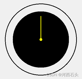
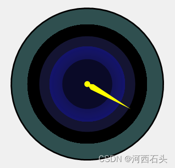
有了前面的坐标相关知识的了解,我们这次来实战一把,绘制一个表盘。当然,绘制表盘我们要学会GDI+绘图中的路径绘图与两个必要的Transform变形函数,RotateTransform(旋转变形)、TranslateTransform(移动变形)。我们先来看看效果:

一、路径
1、GraphicsPath介绍
什么是图形路径呢?用官方的话来说就是“表示一系列相互连接的直线和曲线”,为什么会有这么一个类呢?很显然,以前我们学习的图形类,要么是圆,要么是直线,这个类显然就是要把他们都结合在一起。这个类的使命决定它的用法是比较丰富的,我们可以具体参看官网这里我们来介绍几个比较常用的方法,满足我们后面的绘图需要即可。
2、初识GraphicsPath与基本元素
绘制一个GraphicPath最基本的条件是要拥有绘制的元素,所以GDI+为GraphicPath提供了一大堆的添加元素的方法,都是以Addxxx命名的函数(如:AddArc,AddBezier,AddCuve,AddEllipse,AddLine,AddRectangle,AddString等及他们对应的复数形式方法和AddPie,AddPath,AddPloygon)。他们的用法都很简单,这里举例看看效果(我们准备了一个干净的窗体):
private void drawPath(Graphics gp)
{

    Point[] myArray =
             {
         new Point(30,30),
         new Point(60,60),
         new Point(0,60),
         new Point(30,30)
     };
    GraphicsPath myPath = new GraphicsPath();
    myPath.AddLines(myArray);

    Point[] myArray2 =
             {
         new Point(30,30),
         new Point(0,0),
         new Point(60,0),
         new Point(30,30)
     };
    GraphicsPath myPath2 = new GraphicsPath();
    myPath2.AddLines(myArray2);
    myPath.AddPath(myPath2, true);
    gp.DrawPath(new Pen(Color.Black, 4), myPath);

}
2、StartFigure
StartFigure的作用是不闭合当前图形即开始一个新图形。 后面添加到该路径的所有点都被添加到此新图形中。
一般我们使用StartFigure绘制图形路径基本就三个步骤:
1、实例化一个GraphicPath
2、利用实例的StartFigure方法开启一个形状
3、利用各种Addxxx函数增加图形元素
4、利用实例的StartFigure方法结束一个形状
5、在至少拥有一个Figure后,调用draw函数绘制出来即可。
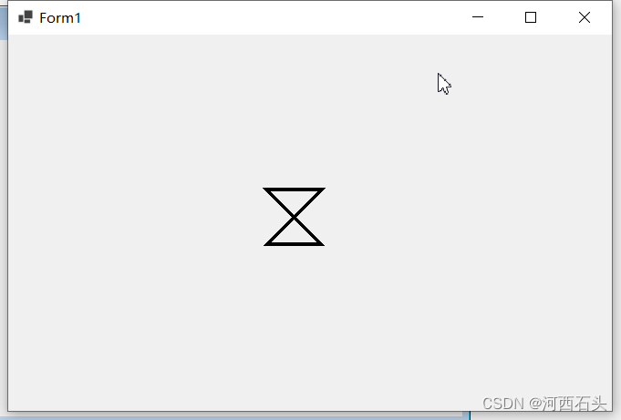
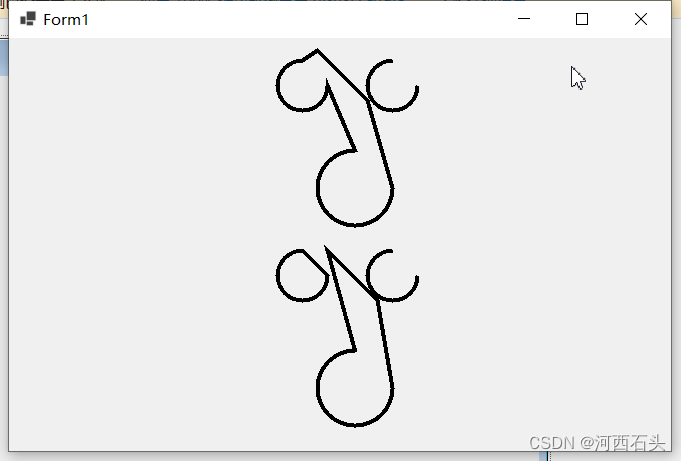
来一个实例:
 private void drawPath(Graphics gp)
 {
     // Create a GraphicsPath object.
     GraphicsPath myPath = new GraphicsPath();
     // First set of figures.
     myPath.StartFigure();
     myPath.AddArc(10, 10, 50, 50, 0, 270);
     myPath.AddLine(new Point(50, 0), new Point(100, 50));
     myPath.AddArc(50, 100, 75, 75, 0, 270);
     myPath.CloseFigure();
     myPath.StartFigure();
     myPath.AddArc(100, 10, 50, 50, 0, 270);

     // Second set of figures.
     myPath.StartFigure();
     myPath.AddArc(10, 200, 50, 50, 0, 270);
     myPath.CloseFigure();
     myPath.StartFigure();
     myPath.AddLine(new Point(60, 200), new Point(110, 250));
     myPath.AddArc(50, 300, 75, 75, 0, 270);
     myPath.CloseFigure();
     myPath.StartFigure();
     myPath.AddArc(100, 200, 50, 50, 0, 270);


     gp.DrawPath(new Pen(Color.Black, 4), myPath);

 }
效果如下:
二、变形函数
1、TranslateTransform与RotateTransform
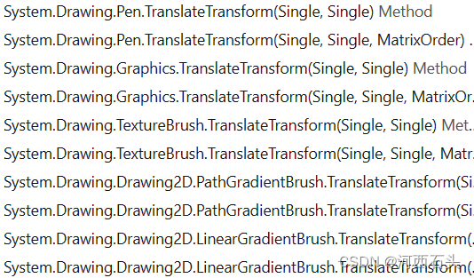
这两个方法存在与Pen、Graphics、TextureBrush、PathGradientBrush、LinearGradientBrush中,当然最常见的还是Graphics中的变形,所以这里我们也将以它为例来演示这个函数的用法。
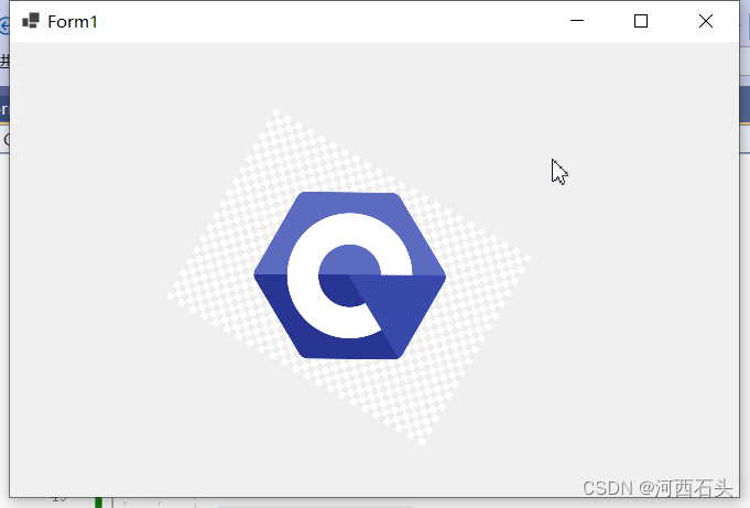
 gp.ResetTransform();
 Image newImage = Image.FromFile("csharp.jpg");
 Point ulCorner = new Point(0, 0);
 gp.TranslateTransform(240, 60);
 gp.ScaleTransform(0.3f, 0.3f);
 gp.RotateTransform(30.0f);
 gp.DrawImage(newImage, ulCorner);
代码一开始,我们重置了图形的变形ResetTransform,以防前面的变形对我们此次变形产生影响。
2、ScaleTransform
我们常用的除了上述两个函数,上面我们还是用了一个ScaleTransform函数,很简单一看就会它专用与缩放,参数接受的是一个浮点型。
三、表盘绘制
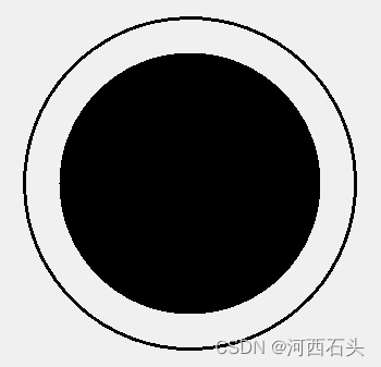
1、圆盘绘制
  graphics.FillEllipse(new SolidBrush(Color.Black), getCircleRect(centerPoint, 120));
  graphics.DrawArc(p, getCircleRect(centerPoint,outlineRadius), mapStartRadias, 360);//绘制一个由clock边框定义的椭圆
2、指针绘制
Point sNeedlePoint = new Point((int)(centerPoint.X + longNeedleLength * Math.Sin(angel_s)), (int)(centerPoint.Y - longNeedleLength * Math.Cos(angel_s)));
graphics.DrawLine(new Pen(Color.Red, 2), centerPoint, sNeedlePoint);
//绘制指针圆柄
graphics.FillEllipse(new SolidBrush(Color.Yellow), getCircleRect(centerPoint, 6));
3、着色知识
1、渐变
关于渐变,如果我们有耐心,可以直接参考官网的说明,为了我们完成目标,我们选择最常用的两种渐变来熟悉一下他们的用法。
(1)、PathGradientBrush
1、初始化PathGradientBrush
2、设定CenterColor
3、设定SurroundColors
4、利用draw绘制渐变
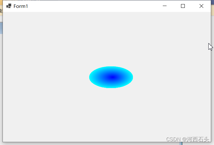
GraphicsPath gp = new GraphicsPath();
gp.AddEllipse(centerPoint.X,centPoint.Y,100,50);
Color[] surroundColor = new Color[] { Color.White};
PathGradientBrush pb = new PathGradientBrush(gp);
pb.CenterColor = Color.Blue;
pb.SurroundColors = surroundColor;
graphics.FillPath(pb, gp);
(2)、LinearGradientBrush
我们首先来看看它的构造函数:
public LinearGradientBrush(Point point1, Point point2, Color color1, Color color2);
public LinearGradientBrush(PointF point1, PointF point2, Color color1, Color color2);
public LinearGradientBrush(Rectangle rect, Color color1, Color color2, LinearGradientMode linearGradientMode);
public LinearGradientBrush(Rectangle rect, Color color1, Color color2, float angle);
public LinearGradientBrush(RectangleF rect, Color color1, Color color2, LinearGradientMode linearGradientMode);
public LinearGradientBrush(RectangleF rect, Color color1, Color color2, float angle);
public LinearGradientBrush(Rectangle rect, Color color1, Color color2, float angle, bool isAngleScaleable);
public LinearGradientBrush(RectangleF rect, Color color1, Color color2, float angle, bool isAngleScaleable);
很显然,这个类的构造函数决定了我们一般有四种方式来使用它;
1、初始化LinearGradientBrush时设定好渐变的起点和终点及对应的两种颜色
2、初始化LinearGradientBrush时设定好的矩形、对应的两种颜色及渐变角度
3、初始化LinearGradientBrush时设定好的矩形、对应的两种颜色及渐变方向(本质同第二种,只是把典型的角度做成了枚举LinearGradientMode )
4、初始化LinearGradientBrush时设定好的矩形、对应的两种颜色、渐变角度及缩放
所以,我们列举了典型了应用,代码如下:
 private void drawPath(Graphics gp)
 {
	LinearGradientBrush linGrBrush = new LinearGradientBrush(
	new Point(0, 10),
    new Point(220, 10),
	Color.FromArgb(255, 255, 0, 0),   // Opaque red
	Color.FromArgb(255, 0, 0, 255));  // Opaque blue

	Pen pen = new Pen(linGrBrush);

	gp.DrawLine(pen, 200, 10, 500, 10);
	gp.FillEllipse(linGrBrush, 240, 20, 200, 100);
	gp.FillRectangle(linGrBrush, 0, 155, 500, 30);


	Point pt=new Point(0, 0);
	Brush b = new LinearGradientBrush(button1.ClientRectangle, Color.Green, Color.Honeydew, 75);//最后一个参数渐变颜色方向或角度,button1窗体中有一个隐藏的按钮
	gp.FillRectangle(b, button1.ClientRectangle);

 }
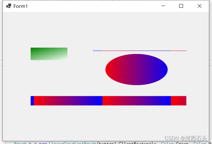
这里尤其要注意,渐变的起点和终点,比如上图的椭圆,起点x=240,长200,颜色的起点一点要能够覆盖这段长度,那么颜色的起点x=230,终点x=450,可算是万无一失。我们看下面的矩形渐变就对渐变起点终点一目了然了。
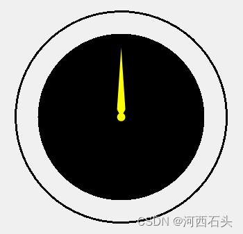
4、 指针着色
Point sNeedlePoint = new Point((int)(centerPoint.X + longNeedleLength * Math.Sin(angel_s)), (int)(centerPoint.Y - longNeedleLength * Math.Cos(angel_s)));
GraphicsPath spath1 = new GraphicsPath();
spath.AddArc(getCircleRect(centerPoint, 6), 0, 360);
Point[] points = { centerPoint, new Point((int)(centerPoint.X + 12 * Math.Sin(angel_s - Math.PI / 6)), (int)(centerPoint.Y - 12 * Math.Cos(angel_s - Math.PI / 6))), sNeedlePoint, new Point((int)(centerPoint.X + 12 * Math.Sin(angel_s + Math.PI / 6)), (int)(centerPoint.Y - 12 * Math.Cos(angel_s + Math.PI / 6))) };
GraphicsPath spath2 = new GraphicsPath();
spath2.AddLines(points);
graphics.FillPath(new SolidBrush(Color.Yellow), spath2);
graphics.FillPath(new SolidBrush(Color.Yellow) , spath1);
5、表盘着色
表盘着色,我们采用的就是fill系列的函数,如FillPath结合渐变,FillEllipse等。所以我们前面的基础要掌握。
g.FillEllipse(new SolidBrush(Color.DarkSlateGray), getCircleRect(centerPoint, 152));
g.FillEllipse(new SolidBrush(Color.Black), getCircleRect(centerPoint, 120));
 g.FillEllipse(new SolidBrush(Color.FromArgb(50, 100, 100, 255)), getCircleRect(centerPoint, 96));
GraphicsPath gp = new GraphicsPath();

gp.AddArc(getCircleRect(centerPoint, 76), 0, 360);
Color[] surroundColor = new Color[] { Color.FromArgb(100, 20, 20, 200)};
PathGradientBrush pb = new PathGradientBrush(gp);
pb.CenterColor = Color.FromArgb(60, 10, 10, 20);
pb.SurroundColors = surroundColor;
g.FillPath(pb, gp);
g.FillEllipse(new SolidBrush(Color.FromArgb(10, 10, 40)), getCircleRect(centerPoint, 50));
g.DrawArc(p, getCircleRect(centerPoint,outlineRadius), mapStartRadias, 360);//绘制边框圆
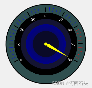
6、增加刻度和文字
g.SmoothingMode = System.Drawing.Drawing2D.SmoothingMode.AntiAlias;
Pen p = new Pen(Color.Black, 3);
Pen k = new Pen(Color.White, 2);
GraphicsPath spath = new GraphicsPath();
 spath.StartFigure();
for (int i = 0; i <= fullGauge / bigUnit; i++)//时刻标度0-12, 30度一格
{
    double angel = i * (Math.PI) / 6;

    Point xy1 = new Point((int)(outlineRadiusOffset * Math.Cos(angelStart + angel) + centerPoint.X), (int)(outlineRadiusOffset * Math.Sin(angelStart + angel) + centerPoint.Y));//圆心定义为(centerPoint.X,centerPoint.Y)
    Point xy2 = new Point((int)(inlineRadiusOffset * Math.Cos(angelStart + angel) + centerPoint.X), (int)(inlineRadiusOffset * Math.Sin(angelStart + angel) + centerPoint.Y));
    Point xystr = new Point((int)(strRadius * Math.Cos(angelStart + angel) + centerPoint.X), (int)(strRadius * Math.Sin(angelStart + angel) + centerPoint.Y));

    g.DrawLine(p, xy1, xy2);
    //刻度文字
    String str = ((i) * 10).ToString();
    SizeF sizeg = g.MeasureString(str, new Font("宋体", 9));
    if ((angelStart + angel) >= Math.PI * 3 / 2)
    {
        if ((angelStart + angel) == Math.PI * 3 / 2)
            g.DrawString(str, new Font("宋体", 9), new SolidBrush(k.Color), new Point(xystr.X - 10, xystr.Y - (int)((sizeg.Height / 3) * Math.Cos(angelStart + angel))));
        else
            g.DrawString(str, new Font("宋体", 9), new SolidBrush(k.Color), new Point(xystr.X - (int)((sizeg.Width) * Math.Cos(angelStart + angel)), xystr.Y - (int)((sizeg.Height / 3) * Math.Cos(angelStart + angel))));
    }
    else
        g.DrawString(str, new Font("宋体", 9), new SolidBrush(k.Color), new Point(xystr.X, xystr.Y + (int)((sizeg.Height / 3) * Math.Cos(angelStart + angel)))); //-(int)((sizeg.Width) * Math.Cos(angelStart + angel)),- (int)((sizeg.Height / 2) * Math.Cos(angelStart + angel))

}
for (int i = 0; i <= fullGauge / smallUnit; i++)//小刻标度0-60
{
    double angel = i * (Math.PI) / 30;

    Point xy1 = new Point((int)(outlineRadiusOffset * Math.Cos(angelStart + angel) + centerPoint.X), (int)(outlineRadiusOffset * Math.Sin(angelStart + angel) + centerPoint.Y));
    Point xy2 = new Point((int)(middleRadiusOffset * Math.Cos(angelStart + angel) + centerPoint.X), (int)(middleRadiusOffset * Math.Sin(angelStart + angel) + centerPoint.Y));

    if (i % 5 != 0)
           spath.AddLine( xy1, xy2);

}
 spath.CloseFigure();
这里要注意,如果我们要实现警告刻度区,那就要分别来绘制刻度线。用一个if语句即可完成。
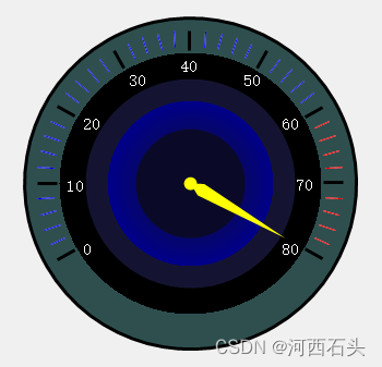
刻度喜欢亮一些可以提亮点,如下图:
可以选择加上一个仪表盘的标签
String strt = "仪表盘";
SizeF sizeF = g.MeasureString(strt, new Font("宋体", 9));
int strFrameEdgeOffset = 4;
g.FillRectangle(new SolidBrush(Color.Gray), new Rectangle(centerPoint.X - ((int)sizeF.Width / 2) - strFrameEdgeOffset, centerPoint.Y + 80- strFrameEdgeOffset, (int)sizeF.Width + strFrameEdgeOffset, (int)sizeF.Height + strFrameEdgeOffset));
g.DrawString(strt, new Font("宋体", 9),new SolidBrush(Color.White),new Point(centerPoint.X-((int)sizeF.Width/2),centerPoint.Y+80));
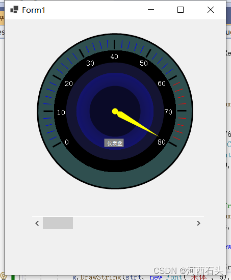
到这里,仪表盘的绘制基本完成,这个时候我们就可以和事件的联系在一起实现转动了。我这里的指针都是使用的可变化的角度,所以可以根据事件的值来变化,就如我们开头看到的那样可以转动。
当然,你完全可以自己新建一个自定义控件,把这些代码拷贝进去,那你就有了一个表盘自定义控件了。