要求:

目录
1、IP规划
2、交换机的配置
2.1 Eth-Trunk通道(将多个接口逻辑的整合成一个接口,实现带宽叠加的作用)
2.2 创建VLAN(所有交换机只创建VLAN2,默认有VLAN1)
2.3 创建trunk干道
2.4 接口划入VLAN
2.5 STP的配置
2.6 配置网关冗余
2.6.1 SVI(交换虚拟接口)
2.6.2 VRRP(网关冗余协议)
2.7 DHCP配置
3、配置路由接口IP
4、SW1/2和r1启用ospf获取路由
5、NAT地址转换测试
6、测试
PC1 ping PC3
PC1 ping PC2
PC2 ping PC4
PC2 ping PC3
PC1访问公网
PC2访问公网
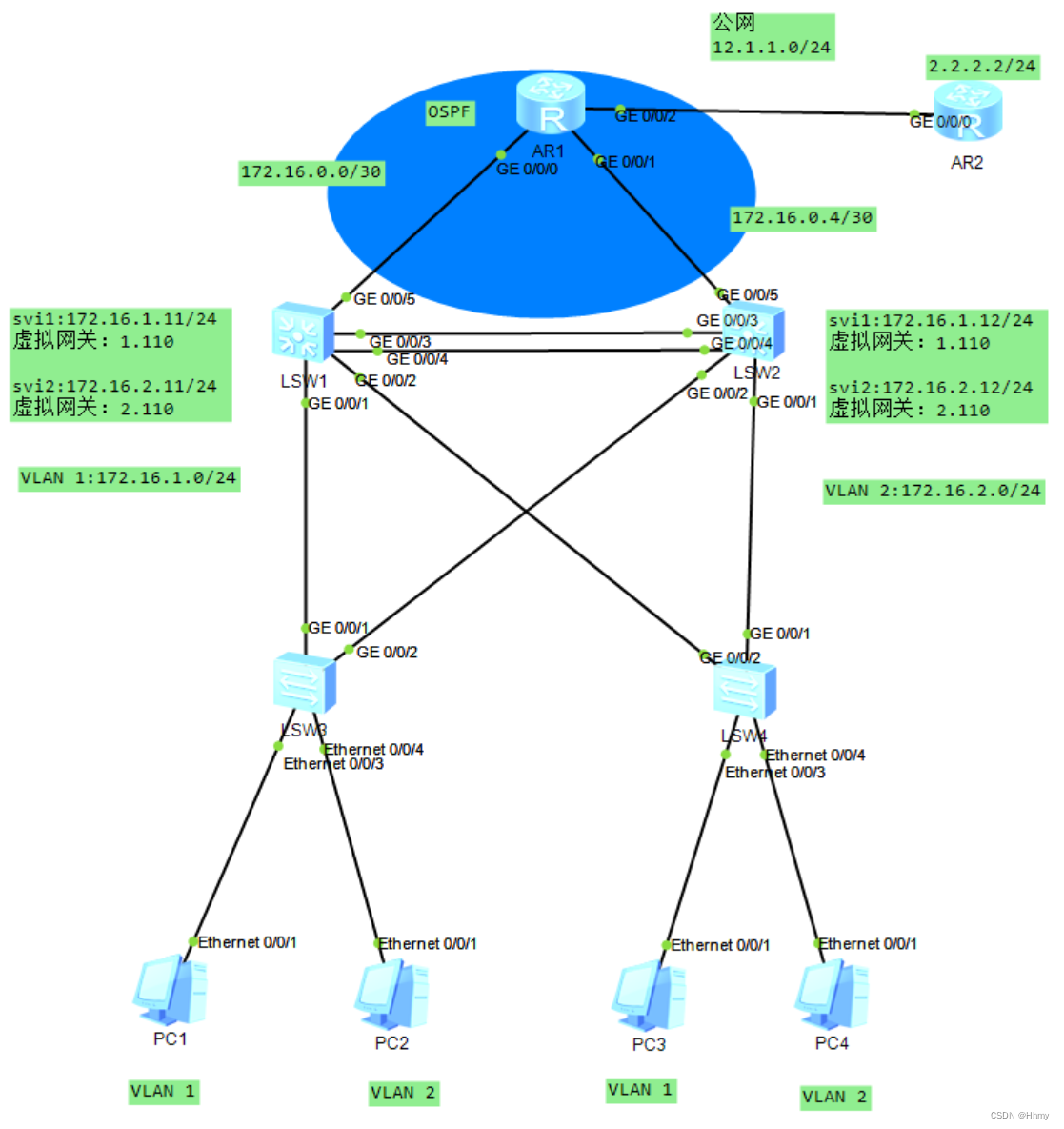
1、IP规划
内网基于 172.16.0.0/16进行划分,实验两个三层交换机各需要一个网段,VLAN1和2也需要两个网段,所以此实验共需要4个网段。
172.16.0.0/24 可用范围 1-31 骨干借到30位预留IP
左边骨干:172.16.0.0/30
右边骨干:172.16.0.4/30
VLAN1:172.16.1.0/24
VLAN2:172.16.2.0/24
2、交换机的配置
步骤:eth-trunk—创建VLAN—trunk干道—接口划入VLAN—STP—SVI—VRRP—DHCP
2.1 Eth-Trunk通道(将多个接口逻辑的整合成一个接口,实现带宽叠加的作用)
SW1和SW2起eth-trunk,并划入接口
[sw1]interface Eth-Trunk 0
[sw1-Eth-Trunk0]int g0/0/3
[sw1-GigabitEthernet0/0/3]eth-trunk 0
[sw1-GigabitEthernet0/0/3]int g0/0/4
[sw1-GigabitEthernet0/0/4]eth-trunk 0
[sw2]interface Eth-Trunk 0
[sw2-Eth-Trunk0]int g0/0/3
[sw2-GigabitEthernet0/0/3]eth-trunk 0
[sw2-GigabitEthernet0/0/3]int g0/0/4
[sw2-GigabitEthernet0/0/4]eth-trunk 0
2.2 创建VLAN(所有交换机只创建VLAN2,默认有VLAN1)
[sw1]vlan 2
[sw2]vlan 2
[sw3]vlan 2
[sw4]vlan 2
2.3 创建trunk干道
[sw1]port-group group-member Eth-Trunk 0 GigabitEthernet 0/0/1 to GigabitEthernet 0/0/2
[sw1-port-group]port link-type trunk
[sw1-Eth-Trunk0]port link-type trunk
[sw1-GigabitEthernet0/0/1]port link-type trunk
[sw1-GigabitEthernet0/0/2]port link-type trunk
[sw1-port-group]port trunk allow-pass vlan 2
[sw1-Eth-Trunk0]port trunk allow-pass vlan 2
[sw1-GigabitEthernet0/0/1]port trunk allow-pass vlan 2
[sw1-GigabitEthernet0/0/2]port trunk allow-pass vlan 2
/ /sw2上同样操作
[sw3]port-group group-member GigabitEthernet 0/0/1 to GigabitEthernet 0/0/2
[sw3-port-group]port link-type trunk
[sw3-GigabitEthernet0/0/1]port link-type trunk
[sw3-GigabitEthernet0/0/2]port link-type trunk
[sw3-port-group]port trunk allow-pass vlan 2
[sw3-GigabitEthernet0/0/1]port trunk allow-pass vlan 2
[sw3-GigabitEthernet0/0/2]port trunk allow-pass vlan 2
/ /sw4上同样操作
2.4 接口划入VLAN
[sw3]int Ethernet0/0/3
[sw3-Ethernet0/0/3]port link-type access
[sw3-Ethernet0/0/3]port default vlan 1
[sw3]int Ethernet0/0/4
[sw3-Ethernet0/0/4]port link-type access
[sw3-Ethernet0/0/4]port default vlan 2
/ /sw4上同样操作
2.5 STP的配置
[sw1]stp enable
[sw1]stp region-configuration
[sw1-mst-region]region-name a
[sw1-mst-region]instance 1 vlan 1
[sw1-mst-region]instance 2 vlan 2
[sw1-mst-region]active region-configuration
/ /在sw2/3/4上做同样操作
我们需要调整根网桥的位置,让SW1成为组1的主根,组2的备份根,让SW2成为组1的备份根,组2的主根
[sw1]stp instance 1 root primary
[sw1]stp instance 2 root secondary
[sw2]stp instance 1 root secondary
[sw2]stp instance 2 root primary
查看生成树接口状态
在连接终端的接口上设置边缘端口,可以加速
[sw3]int eth0/0/3
[sw3-Ethernet0/0/3]stp edged-port enable
[sw3-Ethernet0/0/3]int eth0/0/4
[sw3-Ethernet0/0/4]stp edged-port enable
[sw4]int eth0/0/3
[sw4-Ethernet0/0/3]stp edged-port enable
[sw4-Ethernet0/0/3]int eth0/0/4
[sw4-Ethernet0/0/4]stp edged-port enable
2.6 配置网关冗余
1.在sw1和sw2中创建vlan1和vlan2的svi
2.使用VRRP 协议配置虚拟网关和定义主备设备
2.6.1 SVI(交换虚拟接口)
[sw1]int Vlanif1
[sw1-Vlanif1]ip add 172.16.1.11 24
[sw1]int Vlanif2
[sw1-Vlanif1]ip add 172.16.2.11 24
[sw2]int Vlanif1
[sw2-Vlanif1]ip add 172.16.1.12 24
[sw2]int Vlanif2
[sw2-Vlanif1]ip add 172.16.2.12 24

2.6.2 VRRP(网关冗余协议)
[sw1]int Vlanif 1
[sw1-Vlanif1]vrrp vrid 1 virtual-ip 172.16.1.110
[sw1-Vlanif1]vrrp vrid 1 priority 11
[sw1-Vlanif1]vrrp vrid 1 track interface GigabitEthernet 0/0/5 reduced 10
[sw1-Vlanif1]q
[sw1]int Vlanif 2
[sw1-Vlanif2]vrrp vrid 1 virtual-ip 172.16.2.110
[sw2]int Vlanif 1
[sw2-Vlanif1]vrrp vrid 1 virtual-ip 172.16.1.110
[sw2-Vlanif1]q
[sw2]int Vlanif 2
[sw2-Vlanif2]vrrp vrid 2 virtual-ip 172.16.2.110
[sw2-Vlanif2]vrrp vrid 2 priority 11
[sw2-Vlanif2]vrrp vrid 2 track interface GigabitEthernet 0/0/5 reduced 10
查看SW1
查看SW2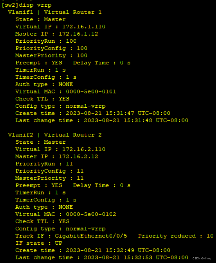
2.7 DHCP配置
[sw1]dhcp enable
[sw1]ip pool v1
[sw1-ip-pool-v1]network 172.16.1.0 mask 24
[sw1-ip-pool-v1]gateway-list 172.16.1.110
[sw1-ip-pool-v1]q
[sw1]int Vlanif 1
[sw1-Vlanif1]dhcp select global
[sw1]int Vlanif 2
[sw1-ip-pool-v2]network 172.16.2.0 mask 24
[sw1-ip-pool-v2]gateway-list 172.16.2.110
[sw1-ip-pool-v2]q
[sw1]int Vlanif 2
[sw1-Vlanif2]dhcp select global
[sw2]dhcp enable
[sw2]ip pool v1
[sw2-ip-pool-v1]network 172.16.1.0 mask 24
[sw2-ip-pool-v1]gateway-list 172.16.1.110
[sw2-ip-pool-v1]q
[sw2]int Vlanif 1
[sw2-Vlanif1]dhcp select global
[sw2-Vlanif1]q
[sw2]ip pool v2
[sw2-ip-pool-v2]network 172.16.2.0 mask 24
[sw2-ip-pool-v2]gateway-list 172.16.2.110
[sw2-ip-pool-v2]q
[sw2]int Vlanif 2
[sw2-Vlanif2]dhcp select global 
3、配置路由接口IP
//配公网IP
[r2]int g0/0/0
[r2-GigabitEthernet0/0/0]ip add 12.1.1.1 24
[r2-GigabitEthernet0/0/0]int lo0
[r2-LoopBack0]ip add 2.2.2.2 24
[r1]int g0/0/2
[r1-GigabitEthernet0/0/2]ip add 12.1.1.2 24
//配私网IP
[r1-GigabitEthernet0/0/2]int g0/0/0
[r1-GigabitEthernet0/0/0]ip add 172.16.0.1 30
[r1-GigabitEthernet0/0/0]int g0/0/1
[r1-GigabitEthernet0/0/1]ip add 172.16.0.5 30
使用svi给sw1和sw2的上行链路g0/0/1接口配置ip
[sw1]vlan 3
[sw1-vlan3]q
[sw1]int Vlanif 3
[sw1-Vlanif3]ip add 172.16.0.2 30
[sw1-Vlanif3]int g0/0/5
[sw1-GigabitEthernet0/0/5]port link-type access
[sw1-GigabitEthernet0/0/5]port default vlan 3
[sw2]vlan 3
[sw2-vlan3]q
[sw2]int Vlanif 3
[sw2-Vlanif3]ip address 172.16.0.6 30
[sw2-Vlanif3]int g0/0/5
[sw2-GigabitEthernet0/0/5]port link-type access
[sw2-GigabitEthernet0/0/5]port default vlan 3
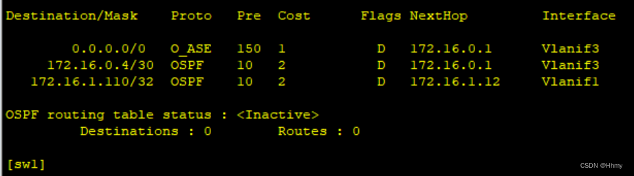
4、SW1/2和r1启用ospf获取路由
[r1]ospf 1 router-id 1.1.1.1
[r1-ospf-1]ar 0
[r1-ospf-1-area-0.0.0.0]network 172.16.0.0 0.0.255.255
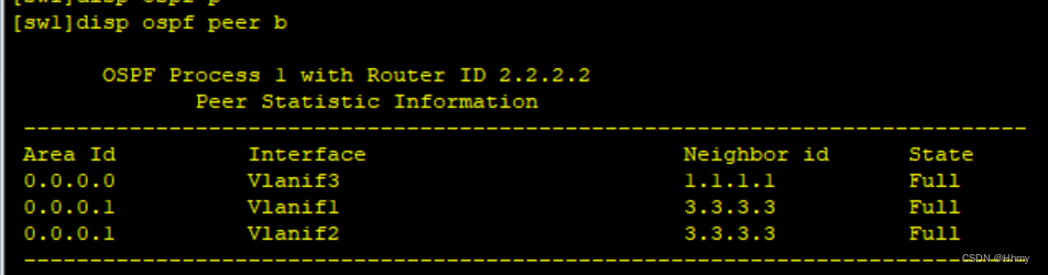
[sw1]ospf 1 router-id 2.2.2.2
[sw1-ospf-1]ar 0
[sw1-ospf-1-area-0.0.0.0]ne
[sw1-ospf-1-area-0.0.0.0]network 172.16.0.2 0.0.0.0
[sw1-ospf-1-area-0.0.0.0]q
[sw1-ospf-1]ar 1
[sw1-ospf-1-area-0.0.0.1]network 172.16.1.0 0.0.0.255
[sw1-ospf-1-area-0.0.0.1]network 172.16.2.0 0.0.0.255
[sw2]ospf 1 router-id 3.3.3.3
[sw2-ospf-1]ar 0
[sw2-ospf-1-area-0.0.0.0]network 172.16.0.6 0.0.0.0
[sw2-ospf-1-area-0.0.0.0]q
[sw2-ospf-1]ar 1
[sw2-ospf-1-area-0.0.0.1]network 172.16.1.0 0.0.0.255
[sw2-ospf-1-area-0.0.0.1]network 172.16.2.0 0.0.0.255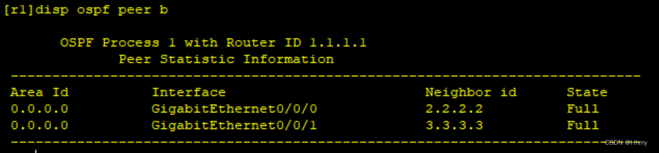
把仅接收不发送路由协议信息的接口调成沉默接口
[sw1-ospf-1]silent-interface g0/0/1
[sw1-ospf-1]silent-interface g0/0/2
[sw1-ospf-1]silent-interface Vlanif 2
[sw2-ospf-1]silent-interface g0/0/1
[sw2-ospf-1]silent-interface g0/0/2
[sw2-ospf-1]silent-interface Vlanif 2

边界路由器需要手动在R1上写一条到达ISP的缺省路由,然后向内网下放一条缺省

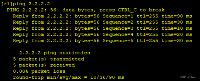
5、NAT地址转换测试
[r1]acl 2000
[r1-acl-basic-2000]rule permit source 172.16.0.0 0.0.255.255
[r1-acl-basic-2000]q
[r1]int g0/0/2
[r1-GigabitEthernet0/0/2]nat outbound 2000
6、测试
PC1 ping PC3

PC1 ping PC2

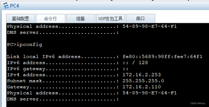
PC2 ping PC4

PC2 ping PC3

PC1访问公网
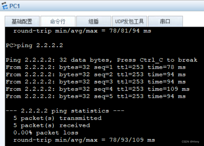
PC2访问公网