AutoSAR基础:Port与Dio配置
- 一.配置port
- 1.Configurator
- 1-1.进入Basic Editor->Port
- 1-2.配置P00.0脚
- 1-2-1.Port口
- 1-2-2.Pin脚配置
- 1-3.配置P00.1
- 1-3-1.Pin脚配置
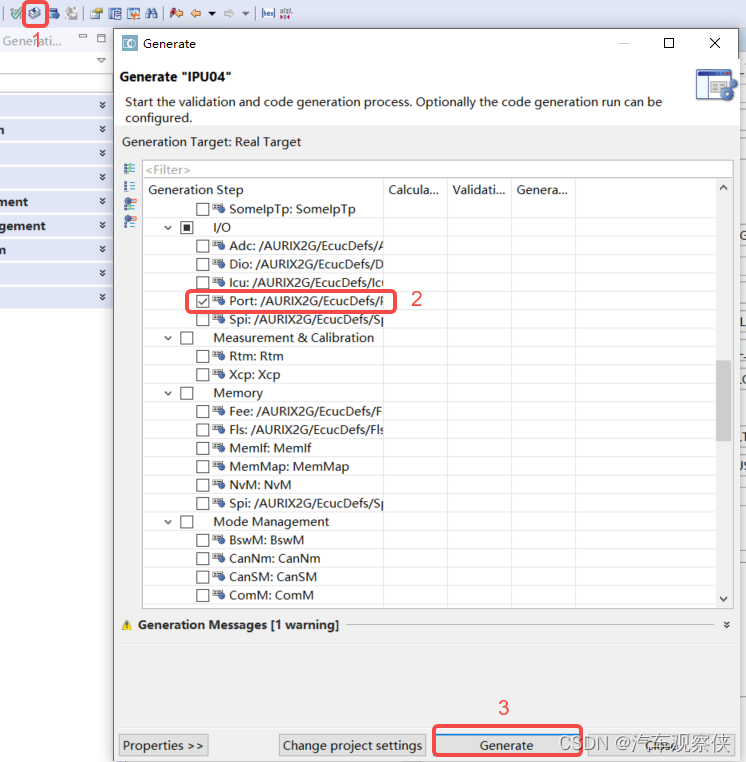
- 2.config导出生成代码
- 3.代码部分
- 3-1.config生成代码
- 3-2.Write与Read
- 3-2-1.Read函数
- 3-2-2.Write函数
- 二.配置Dio
- 1.Configurator
- 1-1.进入Basic Editor->Dio
- 1-2.定义Dio口
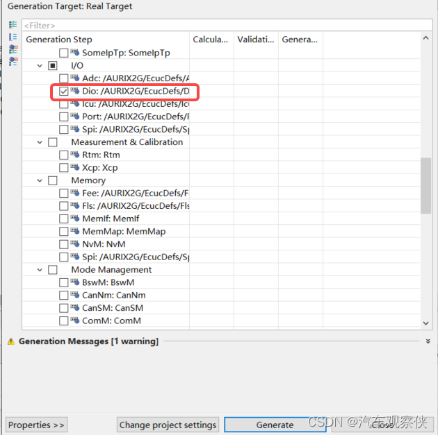
- 2.Config导出代码
- 3.代码部分
一.配置port
MCU的管脚操作程序主要以AutoSAR生成为主,熟料配置Port是AutoSAR架构下MCU开发的基础。
1.Configurator
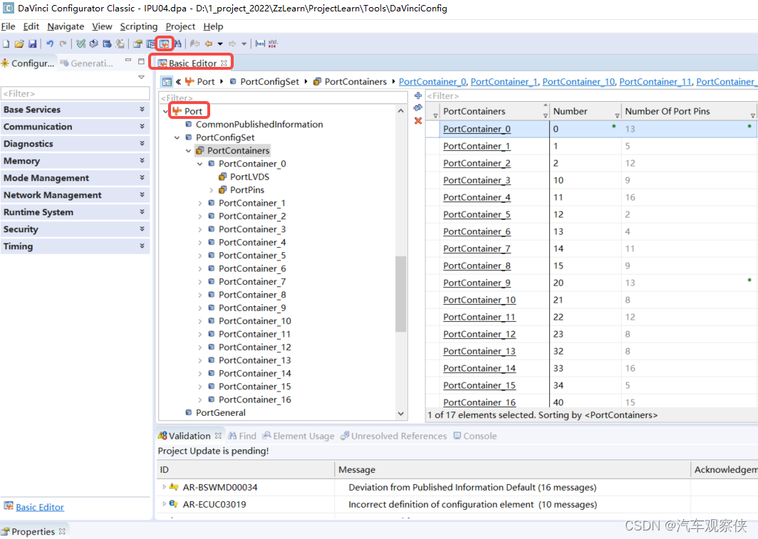
1-1.进入Basic Editor->Port
结合Infineon-TC39x-DataSheet-v01 手册可以,TC397具有17组普通port口
1-2.配置P00.0脚
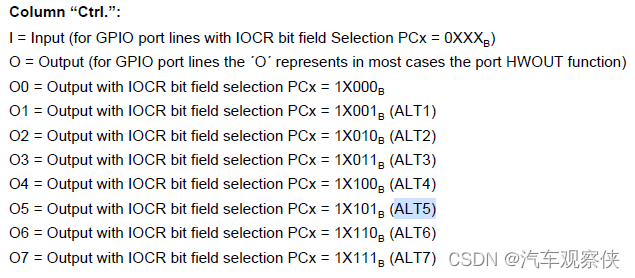
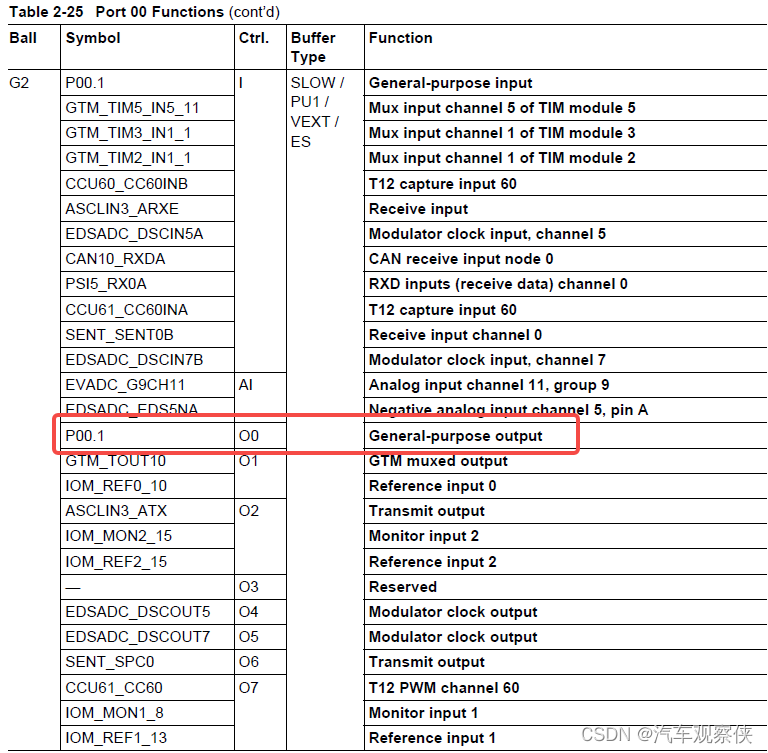
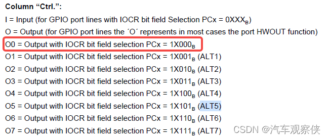
把P00.0配置为CAN10_TXD通信脚。
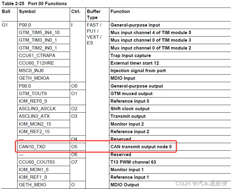
ALT5指代O5:
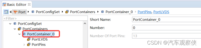
1-2-1.Port口
在Short Name处填入合适的名称;
	在Number处填入port口编号,仅便于识别Port用;
	在Number Of Port Pins处填入该组的管脚个数;
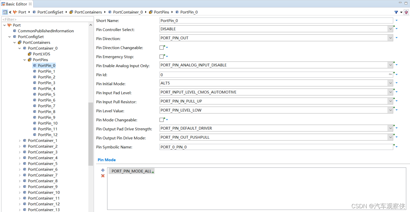
1-2-2.Pin脚配置
pin controller select选择DISABLE,统一不使能控制器选择;
Pin Direction选择PIN脚OUT/IN(输出与输入)模式;
pin enable analog input only(引脚只允许模拟输入),作为普通管脚选择DISABLE(不使能);
pin Id填入PIN脚号,该为0组第0号脚所以填入0;
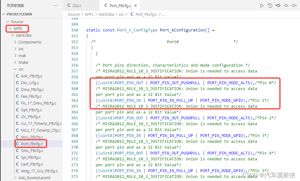
pin Inittial Mode结合图2与图3可知,配置为CAN的TXD选择ALT5;
pim Output Pin Driver Mode选择输出方式,此处选择推挽输出;
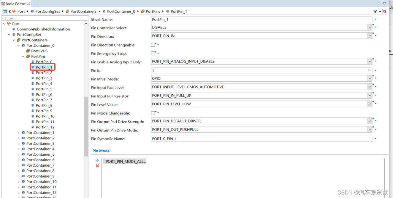
1-3.配置P00.1
1-3-1.Pin脚配置
pin controller select选择DISABLE,统一不使能控制器选择;
Pin Direction选择PIN脚OUT/IN(输出与输入)模式,此处选择为输入模式;
pin enable analog input only(引脚只允许模拟输入),作为普通管脚选择DISABLE(不使能);
pin Id填入PIN脚号,该为0组第1号脚所以填入1;
pin Inittial Mode结合图6与图7可知,配置为普通管脚GPIO;
pin Input Pull Resistor(引脚输入拉阻器)此处选择管脚为上拉输入模式;
pin Level Value(引脚电平值)选择LOW;
2.config导出生成代码
3.代码部分
3-1.config生成代码
3-2.Write与Read
//写
void Dio_WriteChannel(const Dio_ChannelType ChannelId,const Dio_LevelType Level);
//读
typedef uint8 Dio_LevelType;
Dio_LevelType Dio_ReadChannel(const Dio_ChannelType ChannelId);
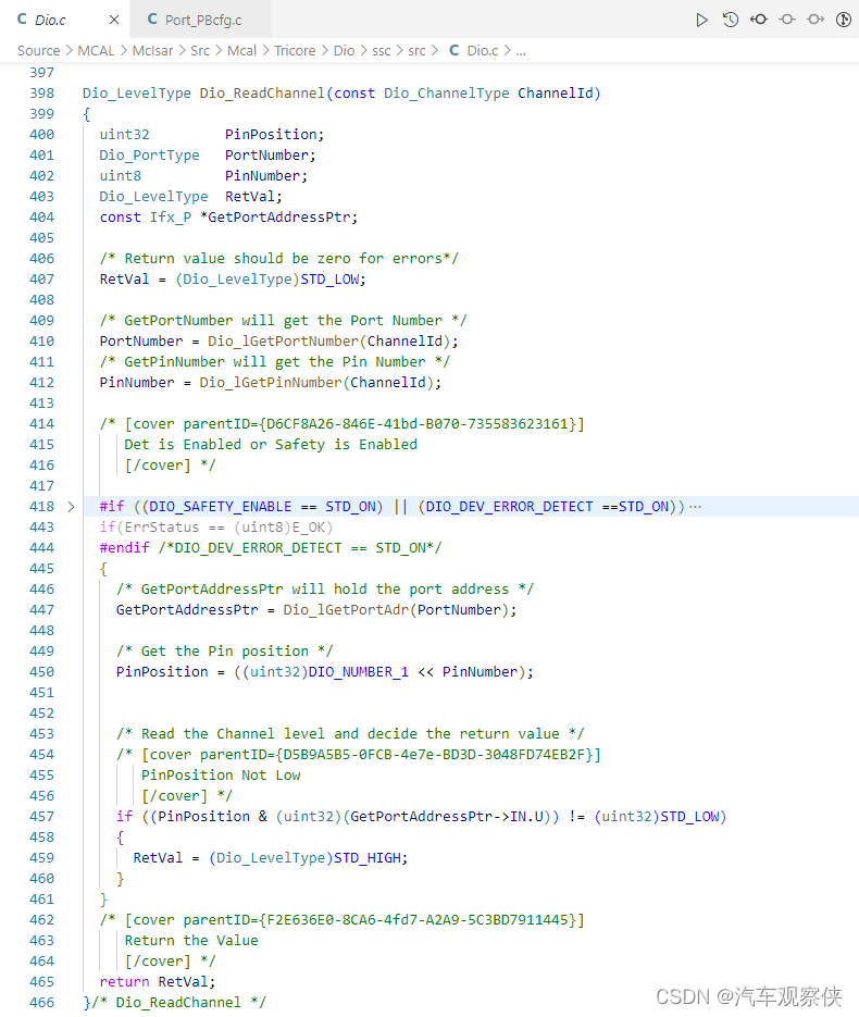
3-2-1.Read函数
以P23.6脚为例:
	Dio_LevelType Port_Type;
	Port_Type = Dio_ReadChannel(0x176);//0x17=23,0x6=6为P23.6
	第410行:PortNumber = Dio_lGetPortNumber(ChannelId);读取port号0x17=23;
	第412行:PinNumber = Dio_lGetPinNumber(ChannelId);读取PIN脚为0x6=6;
	第447-461行读取处该管脚的电平;
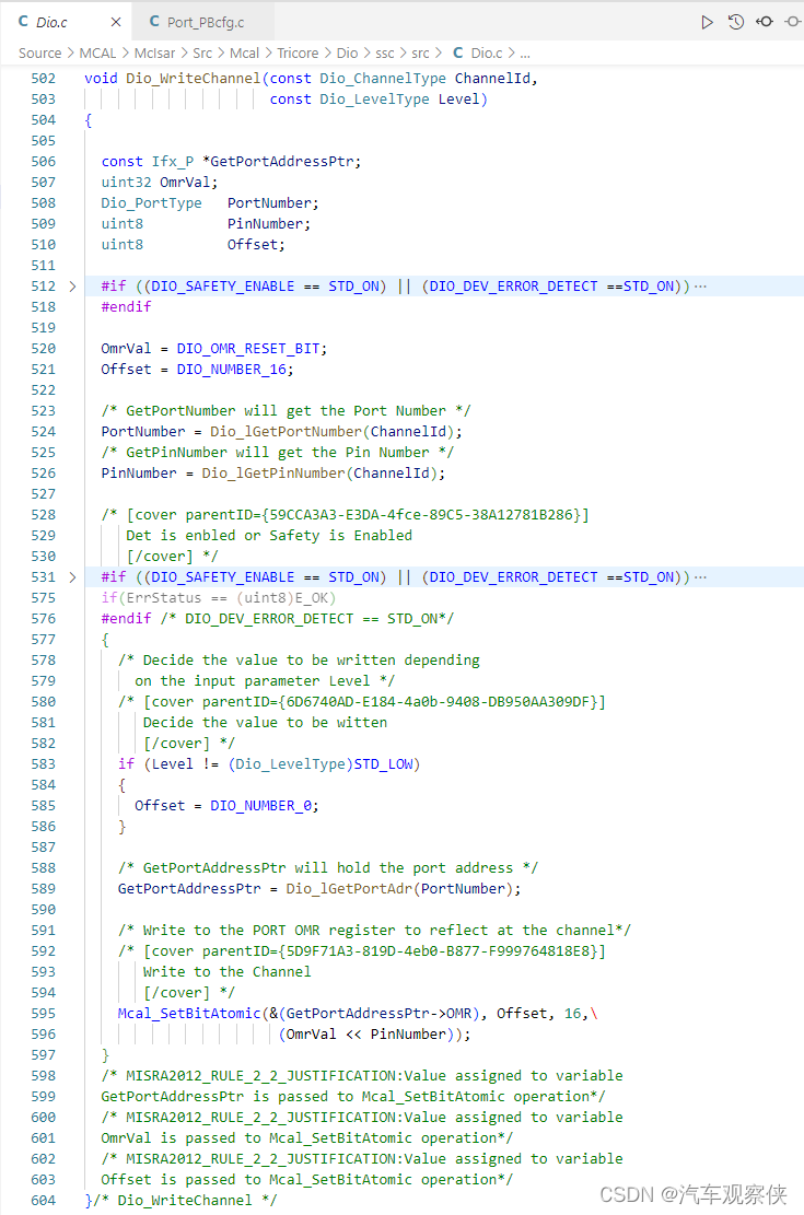
3-2-2.Write函数
以P23.6脚为例:
	Dio_WriteChannel(0x176,1);//0x176指代P23.6脚;1为输出高,可知0为输出低;
	第524行:PortNumber = Dio_lGetPortNumber(ChannelId);读取port号0x17=23;
	第526行:PinNumber = Dio_lGetPinNumber(ChannelId);读取PIN脚为0x6=6;
	第538-597行设置该管脚的电平;
二.配置Dio
Dio主要为Port定义后的管脚定义别名,便于程序调用。
1.Configurator
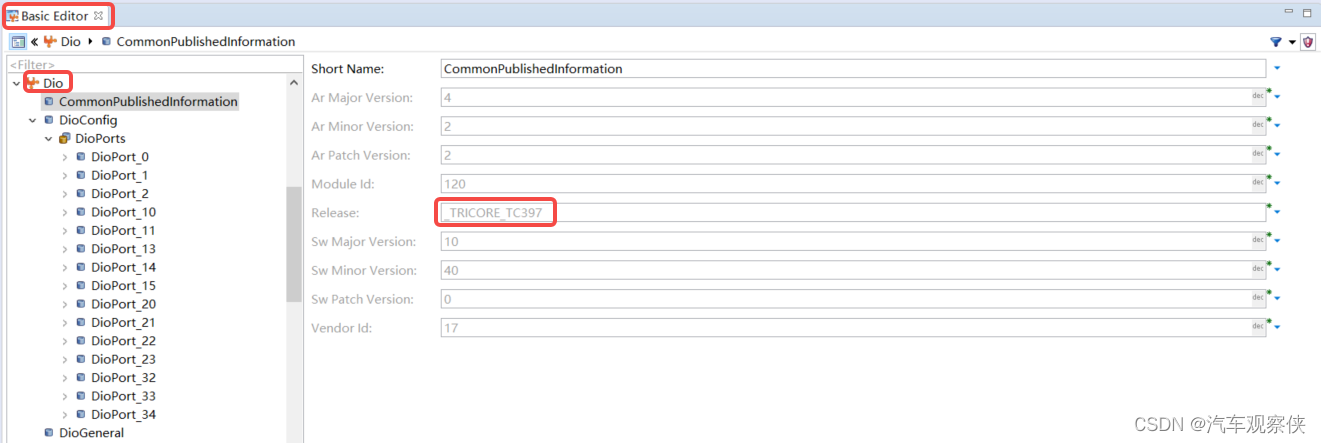
1-1.进入Basic Editor->Dio
定义IC为TC397
定义Port Id号
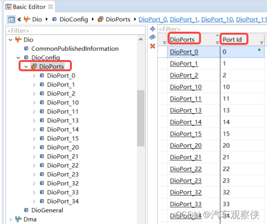
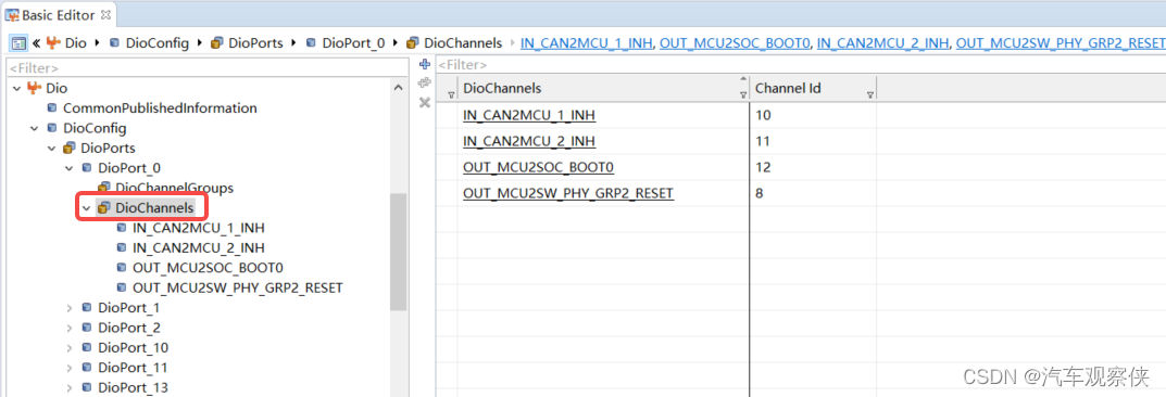
1-2.定义Dio口
Dio是对Port的别名定义
在Port0组内IN_CAN2MCU_1_INH为Pin10号脚。
2.Config导出代码
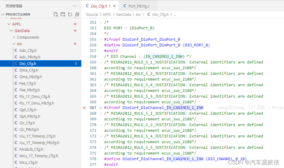
3.代码部分
IN_CAN2MCU_1_INH为P00.10脚。
读写函数同3-2-1与3-2-2 :
读:
Dio_LevelType Port_Type;
Port_Type = Dio_ReadChannel(DioConf_DioChannel_IN_CAN2MCU_1_INH);
写:
Dio_WriteChannel(DioConf_DioChannel_IN_CAN2MCU_1_INH,1);
![[附源码]计算机毕业设计基于SpringBoot的校园报修平台](https://img-blog.csdnimg.cn/4db374525d9f4ba593911464638dc7e7.png)
![[附源码]Python计算机毕业设计Django人员信息管理](https://img-blog.csdnimg.cn/e965403684be41da973c2f2958a79c77.png)