CANN/asc-devkit HCCL算法分析器指南
news2026/5/22 9:34:50
Algorithm Analyzer User Guide【免费下载链接】asc-devkit本项目是CANN 推出的昇腾AI处理器专用的算子程序开发语言原生支持C和C标准规范主要由类库和语言扩展层构成提供多层级API满足多维场景算子开发诉求。项目地址: https://gitcode.com/cann/asc-devkitTool IntroductionThe HCCL algorithm analyzer simulates HCCL algorithm execution in an offline environment. It verifies algorithm logic and memory operations, and efficiently executes test tasks to meet developer requirements.Principle IntroductionKey Points:The algorithm analyzer stubs the dependencies (hcomm and runtime interfaces) of the HCCL single operator execution flow. During algorithm execution, it captures Task sequences from all ranks.It organizes Task information from all ranks into adirected acyclic graph.It performs validations based ongraph algorithms, such as memory read-write conflict validation and semantic validation.Memory conflict validation analyzes whether potential read-write conflicts exist based on synchronization in the graph.Semantic validation simulates Task graph execution and recordsdata transfer information. After simulation completes, it checks whether thedata transfer informationin UserOutput memory meets the operator requirements.Environment PreparationFollow the environment preparation, source code download, compilation, and installation steps in Source Code Build to prepare for algorithm analyzer compilation.Test Case WritingLLT Test Case OverviewAn algorithm checker test case consists of 5 steps, as shown below. The following sections describe how to write each step to accommodate different operator requirements. Finally, it explains how to use the checker tool for issue diagnosis.LLT Test Case Step DetailsSimulation Model InitializationTopoMeta Structure IntroductionThe checker uses TopoMeta to represent a topology. TopoMeta is a three-layer vector structure.PhyDeviceId represents the physical ID of an NPU.ServerMeta consists of PhyDeviceIds and represents the number of cards in a server and their corresponding PhyDeviceIds.SuperPodMeta consists of ServerMetas and represents the servers that form a super node.TopoMeta represents the overall topology of the cluster.TopoMeta Generation MethodsThere are two ways to generate TopoMeta:Specify the number of super nodes, servers, and cards per server, then use the provided GenTopoMeta function to generate it. This applies to symmetric topology scenarios.Fully customize super nodes, servers, and card counts. This applies to both symmetric and asymmetric topology scenarios, as shown below.Model InitializationPass in the generated TopoMeta and specify the device type for simulation.Operator Parameter SettingsOperator Execution ParametersUsing Scatter as an example, you need to set some input parameters for executing the HcclScatter operator and validation. The specific parameters are:root: Set the root node. The Scatter operation distributes data from the root node in the communication domain evenly to other Ranks.rankSize: The number of Ranks participating in collective communication in this communication domain (must be consistent with the number of cards in topoMeta).recvCount: The amount of data each Rank receives from the root node.dataType: The data type corresponding to recvCount.For other operators or custom operator scenarios, set parameters according to the operator requirements.Set Environment VariablesEnvironment variables affect judgment logic in the code. Use the setenv function to set the required conditions before test case execution.Important NotesSupported operators: Currently only the scatter operator is supported.Supported modes: Currently only OPBASE single operator mode is supported.Supported device types: Currently only DEV_TYPE_910B and DEV_TYPE_91093 (represents DEV_TYPE_910C) are supported.Operator Execution FlowAs shown below, run the single operator flow in a multi-threaded manner.Construct operator input parameters.Construct the parameters required for single operator execution, including:SetDevice: Binds a thread to a Rank so that each thread simulates a corresponding Rank.Main stream resource creation: Call the aclrtCreateStream interface, with stub implementation to simulate stream resource creation.Communication domain initialization: Call HcclCommInitClusterInfo, with stub implementation to simulate communication domain creation.Input/output memory allocation: Call aclrtMalloc, with stub implementation to simulate memory creation and mark memory types. Users must calculate the required memory in bytes based on operator type, quantity, and data type.Operator dispatch.Call the HcclScatter operator and pass in the constructed parameters above. For custom operator scenarios, replace this with the custom operator API and modify the operator parameters above to match the custom operator requirements.Communication domain destruction.Call the HcclCommDestroy interface to destroy the communication domain.Result Graph ValidationGet the Task queue from all Ranks and call the corresponding operator validation function. For the Scatter operator, call CheckScatter and pass in the Task queue and the parameters required for Scatter operator validation. The gtest framework prints based on the validation result return value.Resource CleanupThe final step of a single test case execution is to clean up simulation model resources to avoid interference with the next test case execution.Test Case Filtering and DebuggingWhen there are many test cases and you only need to execute one, modify the test case name in main.cc.Test Case Compilation and ExecutionCompile and execute algorithm analyzer test cases:# Enter algorithm analyzer directory /hccl/test/st/algorithm cd ./hccl/test/st/algorithm # Compile test cases and automatically execute bash build.shResult ExampleTest case execution results are shown below:The meaning of each field:[run]: Indicates the test case being executed for validation[OK]: Indicates successful execution, validation passed[FAIL]: Indicates execution failure. Analyze the specific reason based on console logs.Issue DiagnosisMemory Conflict Validation Diagnosis MethodIssue PhenomenonMemory conflicts occur when a memory region between two synchronization signals is written concurrently by multiple tasks, or is written while being read. In actual runtime environments, this typically manifests as randomly occurring precision issues.Under the current Mesh structure, if a Reduce operator exists, false positives may occur. The reason is that under Mesh structure, a memory block may be written by other cards simultaneously within one synchronization. Hardware ensures the atomicity of Reduce operations, so no precision issues occur in actual runtime. However, from the checkers perspective, multiple read-write operations on the same memory between two synchronizations are detected, so it is flagged as an error.Except for the above scenario, if the following error appears, it indicates a memory conflict risk in task scheduling:[1]there is memory use confilict in two SliceMemoryStatus [2]one is startAddr is 0, size is 3200, status is WRITE. [3]another is startAddr is 0, size is 3200, status is WRITE. [4]failed to check memory BufferType::OUTPUT_CCL [5]memory conflict between node [rankId:1, queueId:0, index:1] and node [rankId:2, queueId:0, index:1] [6]check rank memory conflict failed for rank 0Lines 2 and 3 indicate the start address (startAddr), size, and read/write status (status) of the two conflicting memory blocks.status has two states: READ and WRITE. READ indicates the memory block is being read, WRITE indicates the memory block is being written. Being read and being written are abstract memory operation semantics, not just write task and read task.Memory blocks that may be in READ status include: localcopy task src, read task src, write task src. Memory blocks that may be in WRITE status include: localcopy task dst, read task dst, write task dst.Line 4 indicates the type of the conflicting memory block.Line 5 indicates which two tasks caused the memory conflict.Line 6 indicates the rank number where the memory conflict occurred.The above error log indicates that two tasks are simultaneously performing write operations to the range 0-3200 of OUTPUT_CCL type.Diagnosis MethodBased on the error log, find the two tasks that caused the memory conflict and investigate the synchronization scheduling before and after these two tasks.The error log in Issue Phenomenon indicates that two tasks are simultaneously performing write operations to the range 0-3200 of OUTPUT_CCL type.Semantic Validation Failure Diagnosis MethodSemantic Validation Basic ConceptsThe algorithm analyzer uses relative addresses to represent memory, composed of three fields: memory type, offset address, and size, represented by the DataSlice struct:class DataSlice { public: // Some method functions private: BufferType type; u64 offset; u64 size; }Memory supports types such as Input, Output, and CCL.Collective communication algorithms involve complex data transfer and reduction operations during execution. The algorithm analyzer usesBufferSemanticto recorddata transfer relationships, which includes a destination memory expression and multiple source memory expressions. The destination memory is represented by member variables startAddr and Size. The source memory is represented by the SrcBufDes struct, defined as follows:struct BufferSemantic { u64 startAddr; mutable u64 size; // Size, source and destination memory share the same size mutable bool isReduce; // Whether reduction is performed, true when srcBufs has multiple entries mutable HcclReduce0p reduceType; // Type of reduction operation mutable std::setSrcBufDes srcBufs; // Which rank(s) this data comes from }; struct SrcBufDes { RankId rankId; // Source rankId BufferType bufType; // Source memory type mutable u64 srcAddr; // Offset address relative to source memory type };Semantic Calculation ExampleThe following example explains what semantic calculation is.Initial state: There are two Ranks, Rank0 and Rank1, with two memory types, Input and Output.State one action: Transfer the data block from rank0s Input with offset address 20 and size 30 to rank0s Output with offset address 35. Result: A semantic block is generated on rank0s Output, recording this transfer information.State two action: Transfer the data block from rank1s Input with offset address 70 and size 15 to rank0s Output with offset address 50. Result: The destination memory overlaps with an existing semantic block, requiring the existing semantic block to be split, generating two semantic blocks.Result ValidationDuring semantic analysis execution, many semantic blocks are generated (recording many data transfer relationships). After execution completes, validate whether the semantic blocks in Output memory meet expectations.The following example uses 2-rank AllGather to illustrate normal and abnormal scenarios for semantic blocks in Rank0s Output memory. Assume input data size is 100 bytes.Correct Scenario:Error Scenario:Diagnosis ApproachThe semantic validation phase can detect two types of errors:Missing data.Incorrect data source.Extended to reduction scenarios, similar issues exist, such as missing ranks participating in reduction, inconsistent data offset addresses participating in reduction, and so on. Normally, when semantic errors occur, the system provides certain hints. You need to use these hints combined with the task sequence printed by the algorithm analyzer for specific analysis.【免费下载链接】asc-devkit本项目是CANN 推出的昇腾AI处理器专用的算子程序开发语言原生支持C和C标准规范主要由类库和语言扩展层构成提供多层级API满足多维场景算子开发诉求。项目地址: https://gitcode.com/cann/asc-devkit创作声明:本文部分内容由AI辅助生成(AIGC),仅供参考
本文来自互联网用户投稿,该文观点仅代表作者本人,不代表本站立场。本站仅提供信息存储空间服务,不拥有所有权,不承担相关法律责任。如若转载,请注明出处:http://www.coloradmin.cn/o/2634335.html
如若内容造成侵权/违法违规/事实不符,请联系多彩编程网进行投诉反馈,一经查实,立即删除!相关文章
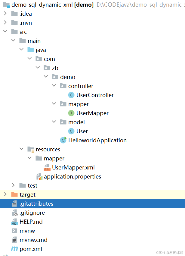
SpringBoot-17-MyBatis动态SQL标签之常用标签
文章目录 1 代码1.1 实体User.java1.2 接口UserMapper.java1.3 映射UserMapper.xml1.3.1 标签if1.3.2 标签if和where1.3.3 标签choose和when和otherwise1.4 UserController.java2 常用动态SQL标签2.1 标签set2.1.1 UserMapper.java2.1.2 UserMapper.xml2.1.3 UserController.ja…
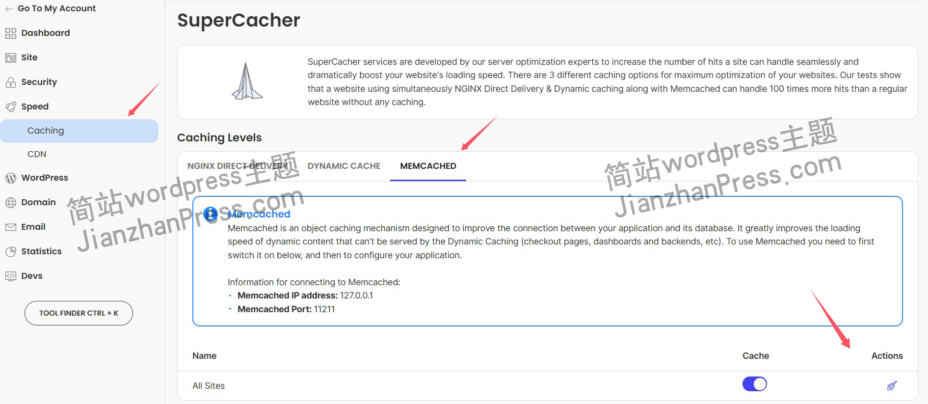
wordpress后台更新后 前端没变化的解决方法
使用siteground主机的wordpress网站,会出现更新了网站内容和修改了php模板文件、js文件、css文件、图片文件后,网站没有变化的情况。
不熟悉siteground主机的新手,遇到这个问题,就很抓狂,明明是哪都没操作错误&#x…
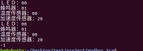
网络编程(Modbus进阶)
思维导图 Modbus RTU(先学一点理论)
概念 Modbus RTU 是工业自动化领域 最广泛应用的串行通信协议,由 Modicon 公司(现施耐德电气)于 1979 年推出。它以 高效率、强健性、易实现的特点成为工业控制系统的通信标准。 包…
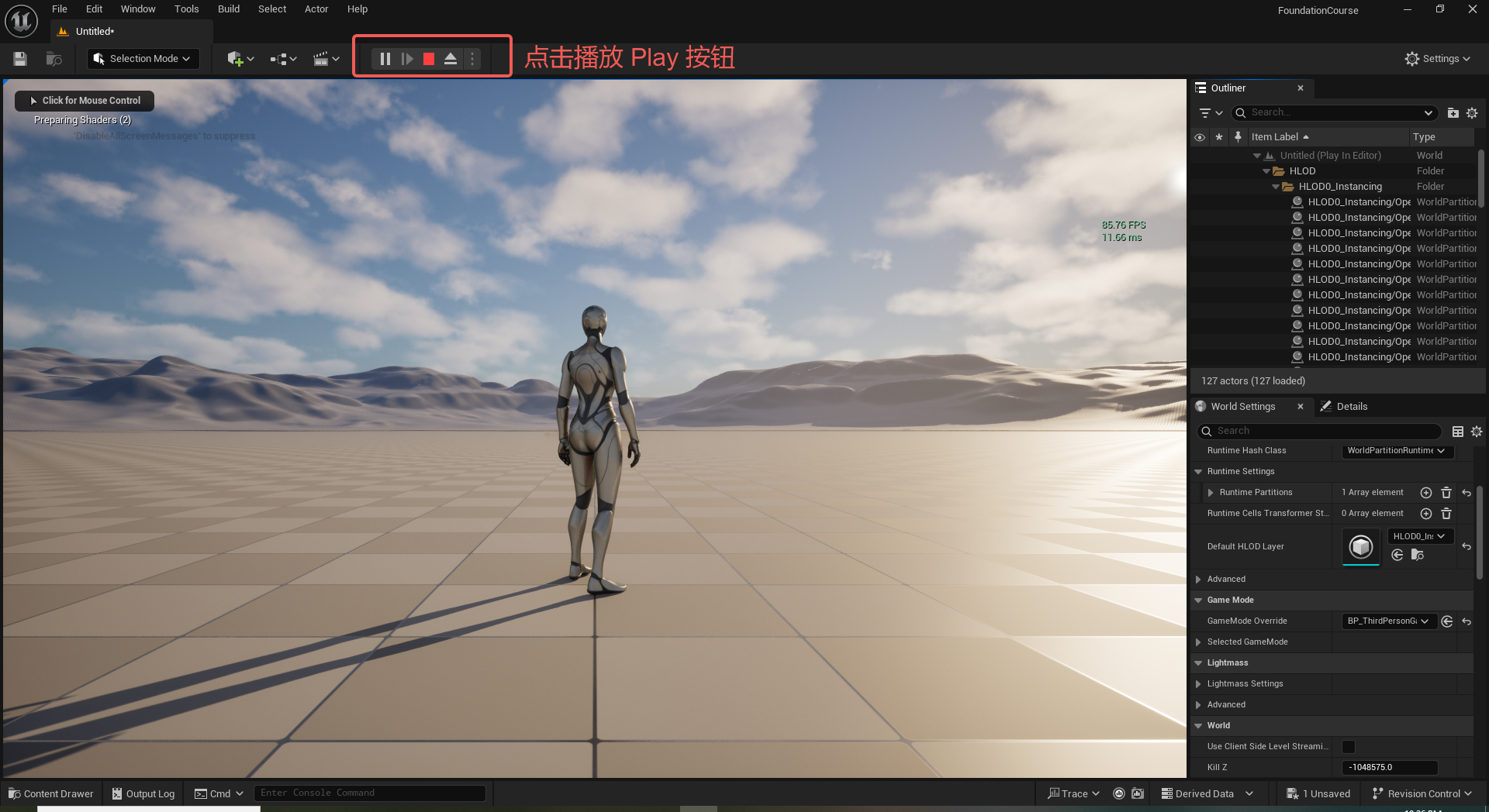
UE5 学习系列(二)用户操作界面及介绍
这篇博客是 UE5 学习系列博客的第二篇,在第一篇的基础上展开这篇内容。博客参考的 B 站视频资料和第一篇的链接如下:
【Note】:如果你已经完成安装等操作,可以只执行第一篇博客中 2. 新建一个空白游戏项目 章节操作,重…
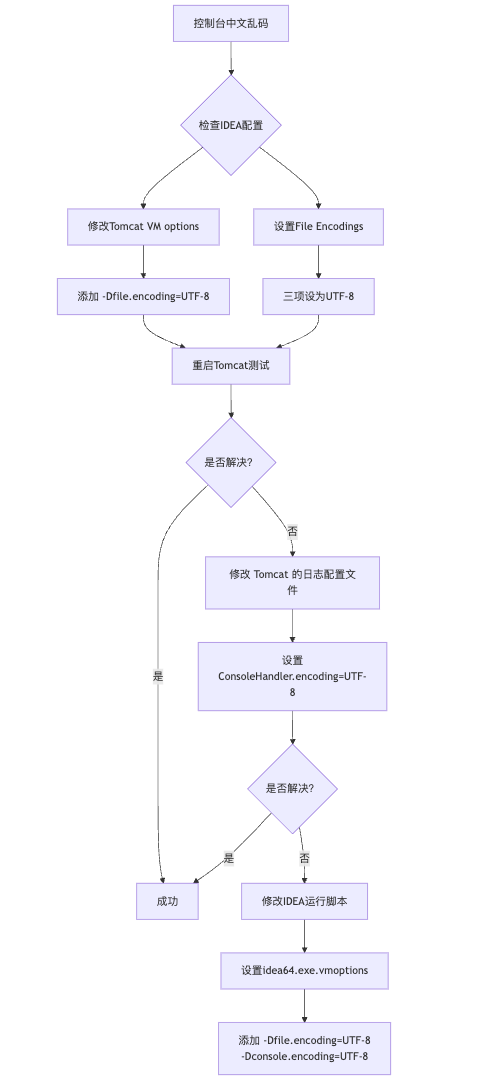
IDEA运行Tomcat出现乱码问题解决汇总
最近正值期末周,有很多同学在写期末Java web作业时,运行tomcat出现乱码问题,经过多次解决与研究,我做了如下整理:
原因:
IDEA本身编码与tomcat的编码与Windows编码不同导致,Windows 系统控制台…
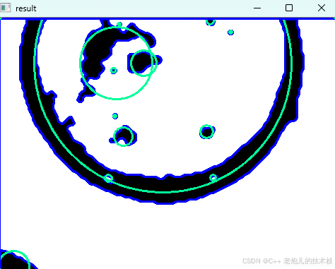
利用最小二乘法找圆心和半径
#include <iostream>
#include <vector>
#include <cmath>
#include <Eigen/Dense> // 需安装Eigen库用于矩阵运算 // 定义点结构
struct Point { double x, y; Point(double x_, double y_) : x(x_), y(y_) {}
}; // 最小二乘法求圆心和半径 …
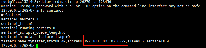
使用docker在3台服务器上搭建基于redis 6.x的一主两从三台均是哨兵模式
一、环境及版本说明
如果服务器已经安装了docker,则忽略此步骤,如果没有安装,则可以按照一下方式安装: 1. 在线安装(有互联网环境): 请看我这篇文章 传送阵>> 点我查看 2. 离线安装(内网环境):请看我这篇文章 传送阵>> 点我查看
说明:假设每台服务器已…
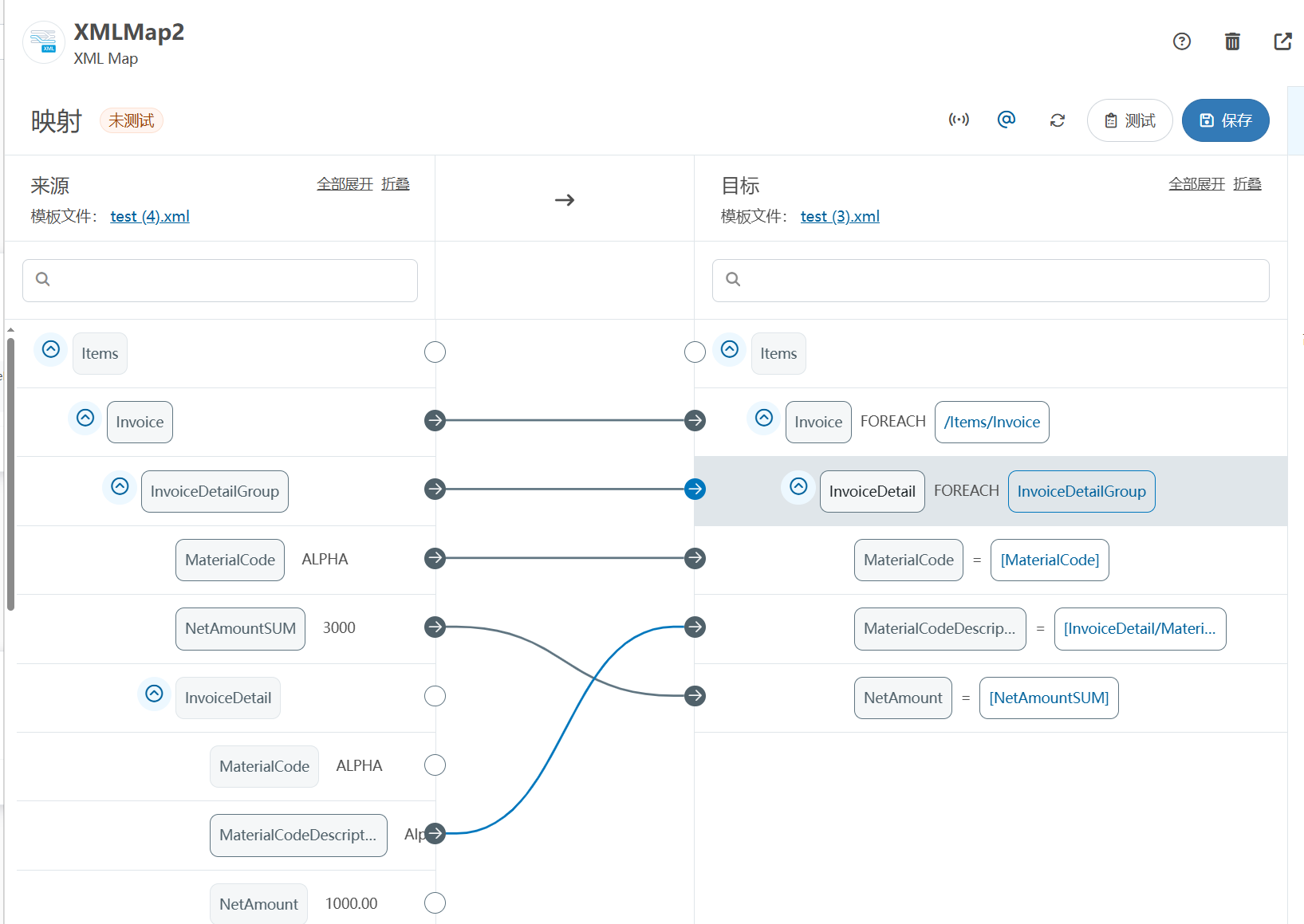
XML Group端口详解
在XML数据映射过程中,经常需要对数据进行分组聚合操作。例如,当处理包含多个物料明细的XML文件时,可能需要将相同物料号的明细归为一组,或对相同物料号的数量进行求和计算。传统实现方式通常需要编写脚本代码,增加了开…
LBE-LEX系列工业语音播放器|预警播报器|喇叭蜂鸣器的上位机配置操作说明
LBE-LEX系列工业语音播放器|预警播报器|喇叭蜂鸣器专为工业环境精心打造,完美适配AGV和无人叉车。同时,集成以太网与语音合成技术,为各类高级系统(如MES、调度系统、库位管理、立库等)提供高效便捷的语音交互体验。
L…
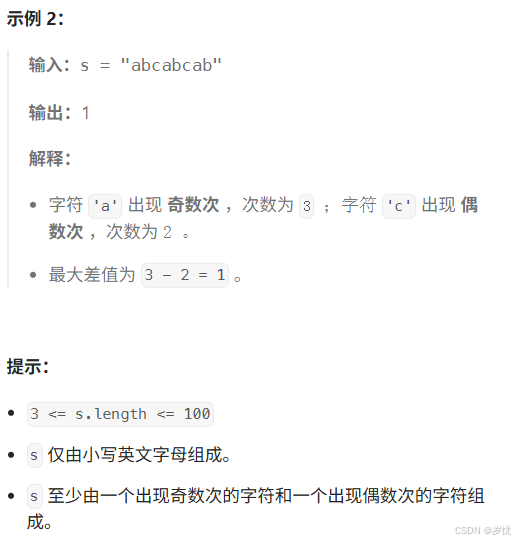
(LeetCode 每日一题) 3442. 奇偶频次间的最大差值 I (哈希、字符串)
题目:3442. 奇偶频次间的最大差值 I 思路 :哈希,时间复杂度0(n)。 用哈希表来记录每个字符串中字符的分布情况,哈希表这里用数组即可实现。
C版本:
class Solution {
public:int maxDifference(string s) {int a[26]…
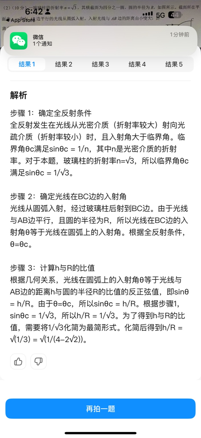
【大模型RAG】拍照搜题技术架构速览:三层管道、两级检索、兜底大模型
摘要
拍照搜题系统采用“三层管道(多模态 OCR → 语义检索 → 答案渲染)、两级检索(倒排 BM25 向量 HNSW)并以大语言模型兜底”的整体框架: 多模态 OCR 层 将题目图片经过超分、去噪、倾斜校正后,分别用…
【Axure高保真原型】引导弹窗
今天和大家中分享引导弹窗的原型模板,载入页面后,会显示引导弹窗,适用于引导用户使用页面,点击完成后,会显示下一个引导弹窗,直至最后一个引导弹窗完成后进入首页。具体效果可以点击下方视频观看或打开下方…
接口测试中缓存处理策略
在接口测试中,缓存处理策略是一个关键环节,直接影响测试结果的准确性和可靠性。合理的缓存处理策略能够确保测试环境的一致性,避免因缓存数据导致的测试偏差。以下是接口测试中常见的缓存处理策略及其详细说明:
一、缓存处理的核…

龙虎榜——20250610
上证指数放量收阴线,个股多数下跌,盘中受消息影响大幅波动。 深证指数放量收阴线形成顶分型,指数短线有调整的需求,大概需要一两天。 2025年6月10日龙虎榜行业方向分析 1. 金融科技
代表标的:御银股份、雄帝科技
驱动…
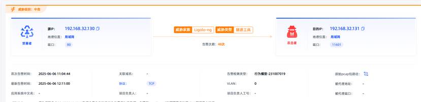
观成科技:隐蔽隧道工具Ligolo-ng加密流量分析
1.工具介绍
Ligolo-ng是一款由go编写的高效隧道工具,该工具基于TUN接口实现其功能,利用反向TCP/TLS连接建立一条隐蔽的通信信道,支持使用Let’s Encrypt自动生成证书。Ligolo-ng的通信隐蔽性体现在其支持多种连接方式,适应复杂网…
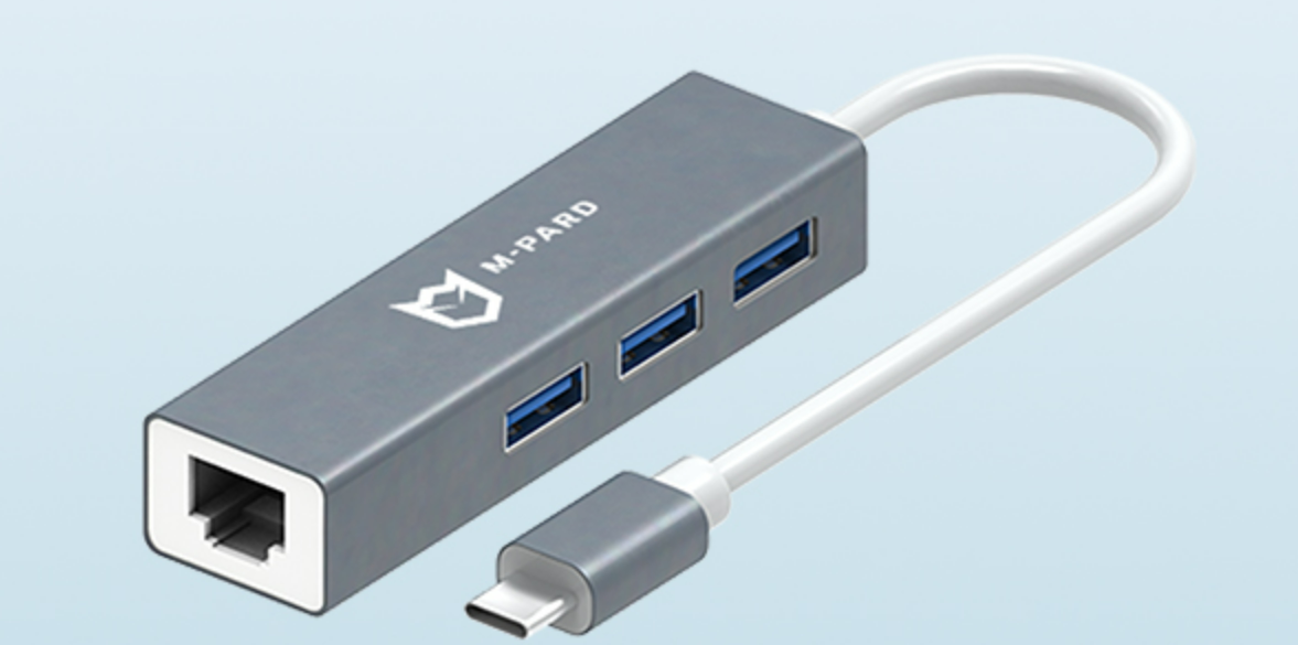
铭豹扩展坞 USB转网口 突然无法识别解决方法
当 USB 转网口扩展坞在一台笔记本上无法识别,但在其他电脑上正常工作时,问题通常出在笔记本自身或其与扩展坞的兼容性上。以下是系统化的定位思路和排查步骤,帮助你快速找到故障原因:
背景:
一个M-pard(铭豹)扩展坞的网卡突然无法识别了,扩展出来的三个USB接口正常。…
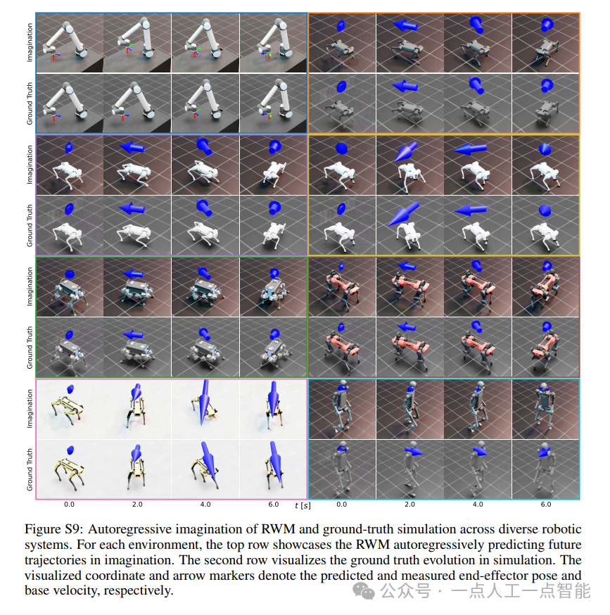
未来机器人的大脑:如何用神经网络模拟器实现更智能的决策?
编辑:陈萍萍的公主一点人工一点智能 未来机器人的大脑:如何用神经网络模拟器实现更智能的决策?RWM通过双自回归机制有效解决了复合误差、部分可观测性和随机动力学等关键挑战,在不依赖领域特定归纳偏见的条件下实现了卓越的预测准…
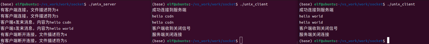
Linux应用开发之网络套接字编程(实例篇)
服务端与客户端单连接
服务端代码
#include <sys/socket.h>
#include <sys/types.h>
#include <netinet/in.h>
#include <stdio.h>
#include <stdlib.h>
#include <string.h>
#include <arpa/inet.h>
#include <pthread.h>
…

华为云AI开发平台ModelArts
华为云ModelArts:重塑AI开发流程的“智能引擎”与“创新加速器”!
在人工智能浪潮席卷全球的2025年,企业拥抱AI的意愿空前高涨,但技术门槛高、流程复杂、资源投入巨大的现实,却让许多创新构想止步于实验室。数据科学家…
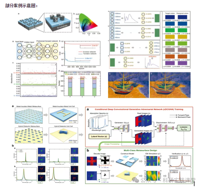
深度学习在微纳光子学中的应用
深度学习在微纳光子学中的主要应用方向
深度学习与微纳光子学的结合主要集中在以下几个方向:
逆向设计 通过神经网络快速预测微纳结构的光学响应,替代传统耗时的数值模拟方法。例如设计超表面、光子晶体等结构。
特征提取与优化 从复杂的光学数据中自…