变压器绕组类型 | 高频变压器绕制要点
news2026/3/27 2:08:41
注本文为 “变压器绕制” 相关合辑。英文引文机翻未校。如有内容异常请看原文。图片清晰度受引文原图所限。变压器绕组类型圆筒式、螺旋式、交叉式与饼式绕组Types of Transformer Windings: Cylindrical, Helical, Crossover Disc WindingJune 21, 2024 by Electrical4UKey learnings:关键要点Types of Transformers: Core type transformers have windings on outer limbs; shell type transformers have windings on inner limbs.变压器类型芯式变压器的绕组绕制在外侧铁芯柱上壳式变压器的绕组绕制在内侧铁芯柱上。Cylindrical Windings: Used for low voltage applications up to 6.6 kV and constructed with layered rectangular or round conductors.圆筒式绕组适用于 6.6 kV 以下低压场景采用分层矩形或圆形导线绕制而成。Helical Windings: Suitable for low voltage, high capacity transformers with types like single, double, and disc-helical windings.螺旋式绕组适用于低压、大容量变压器分为单螺旋、双螺旋和饼式螺旋绕组等类型。Crossover Winding: Used in high voltage small transformers, known for its strength but lower impulse strength.交叉式绕组用于小型高压变压器机械强度较高但冲击耐压性能较低。Disc and Continuous Disc Winding: These are used in high capacity transformers, offering robust construction and improved cooling.饼式与连续饼式绕组用于大容量变压器结构坚固且散热性能优异。Core and Windings of Three Phase Core Type Transformer三相芯式变压器的铁芯与绕组There aredifferent types of windingsused for different kinds of applications and arrangements. Windings are the conductors wrapped in various forms like helical, disc, cylindrical, crossover which generates MMF that is carried by the core to other windings for having the different levels of voltages. Mainly there are two types of transformer:不同应用与结构场景会使用不同类型的绕组。绕组是以螺旋式、饼式、圆筒式、交叉式等形式绕制的导体可产生磁动势磁动势通过铁芯传递至其他绕组从而实现不同等级的电压变换。变压器主要分为两类Core type transformer芯式变压器Shell type transformer壳式变压器In core type, we wrap the primary, and secondary windings on the outside limbs, and in shell type, we place the primary and secondary windings on the inner limbs.芯式变压器的原、副边绕组绕制在外侧铁芯柱上壳式变压器的原、副边绕组则布置在内侧铁芯柱上。We use concentric type windings in core type transformer. We place low voltage winding near to the core. However, to reduce leakage reactance, windings can be interlaced. Winding for core type depends on many factors like current rating, short circuit withstands capacity, the limit of temperature rise, impedance, surge voltage, transport facilities, etc.芯式变压器采用同心式绕组低压绕组靠近铁芯布置为减小漏抗绕组可采用交错布置方式。芯式变压器的绕组设计取决于多项因素包括额定电流、短路耐受能力、温升限值、阻抗、冲击电压、运输条件等。Types of Winding used for Core Type Transformer芯式变压器常用绕组类型Cylindrical Windings圆筒式绕组These windings are layered type and uses a rectangular or round conductor shown in Fig.(a) and (b). The conductors are wound on flat sides shown in Fig.© and wound on the rib side in Fig.(d).该类绕组为分层式结构采用矩形或圆形导线绕制如图(a)、(b)所示导线可扁绕如图©也可立绕如图(d)。Uses of Cylindrical Windings圆筒式绕组的应用Cylindrical windingsare low voltage windings used up to 6.6 kV for kVA up to 600-750, and current rating between 10 to 600 A.圆筒式绕组属于低压绕组适用于电压 6.6 kV 以下、容量 600~750 kVA、额定电流 10~600 A 的场景。We often use cylindrical windings in its multi-layer forms. We use rectangular conductors in two-layered type because it is easy to secure the lead-out ends. Oil ducts separate the layers of the windings this arrangement facilitates the cooling through oil circulation in the winding.圆筒式绕组常采用多层结构双层绕组多选用矩形导线便于引线引出绕组各层之间设置油道通过油液循环实现绕组散热。多层圆筒式绕组采用圆形导线绕制在垂直支撑条上以改善散热条件该结构可形成油道提升散热效果。此类绕组适用于电压最高 33 kV、容量 800 kVA、电流最高 80 A 的高压场景裸导线最大直径为 4 mm。Helical Windings螺旋式绕组We usehelical windingslow voltage, high capacity transformers, where the current is higher, at the same time windings turns are lesser. The output of the transformer varies from 160 – 1000 kVA from 0.23-15 kV. To secure adequate mechanical strength the cross-sectional area of the strip not made less than 75-100 mm square. The maximum number of strips used in parallel to make up a conductor is 16.螺旋式绕组用于大电流、少匝数的低压大容量变压器变压器容量为 160~1000 kVA电压为 0.23~15 kV。为保证足够机械强度导线截面积不小于 75~100 mm²单根导体最多可由 16 根导线并联组成。There are three types:分为三类Single Helical Winding单螺旋绕组Double Helical Winding双螺旋绕组Disc-Helical Winding饼式螺旋绕组Single Helical Windingsconsist of winding in an axial direction along a screw line with an inclination. There is only one layer of turns in each winding. The advantage of Double Helical Winding is that it reduces eddy current loss in conductors. This is on account of the reduced number of parallel conductors situated in the radial direction.单螺旋绕组沿轴向呈倾斜螺旋线绕制每个绕组仅有一层线匝。双螺旋绕组的优势是可减小导线涡流损耗原因是径向并联导线数量减少。InDisc-Helical Windings, parallel strips are placed side by side in a radial direction to cover the entire radial depth of the winding.饼式螺旋绕组中并联导线沿径向并排布置覆盖绕组全部径向厚度。Multi-layer Helical Winding多层螺旋式绕组We use it commonly for high voltage ratings for 110 kV and above. These types of winding consist of several cylindrical layers concentrically wound and connected in series.该绕组常用于 110 kV 及以上高压场景由多个同心圆筒层串联绕制而成。We make the outer layers shorter than the inner layers to distribute capacitance uniformly. These windings primarily improve the surge behavior of transformers.外层长度短于内层可使电容均匀分布该类绕组主要用于改善变压器的冲击电压特性。Crossover Winding交叉式绕组These windings are used in high voltage windings of small transformers. The conductors are paper-covered round wires or strips. The windings are divided into several coils to reduce voltage between adjacent layers. These coils are axially separated by 0.5 to 1 mm, with the voltage between adjacent coils kept within 800 to 1000 V.该绕组用于小型变压器的高压绕组导线采用纸包圆线或扁线绕组分为多个线圈以减小相邻层间电压线圈轴向间距 0.5~1 mm相邻线圈间电压控制在 800~1000 V 以内。The inside end of a coil is connected to the output side end of the adjacent one as shown in the above figure. The actual axial length of each coil is about 50 mm while the spacing between two coils is about 6 mm to accommodate blocks of insulating material.如图所示线圈内端与相邻线圈外端相连。每个线圈实际轴向长度约 50 mm线圈间距约 6 mm用于布置绝缘材料垫块。The width of the coil is 25 to 50 mm. The crossover winding has a higher strength than cylindrical winding under normal conditions. However, the crossover has lover impulse strength than the cylindrical one. This type also has higher labor costs.线圈宽度为 25~50 mm。常规工况下交叉式绕组机械强度高于圆筒式绕组但冲击耐压低于圆筒式绕组且人工成本更高。Disc and Continuous Disc Winding饼式与连续饼式绕组Primarily used for a high capacity transformer. The winding consists of a number of flat coils or discs in series or parallel. The coils are formed with rectangular strips wound spirally from the center outwards in the radial direction as shown in the figure below.主要用于大容量变压器绕组由多个扁平线圈线饼串联或并联组成线圈采用矩形导线由内向外径向螺旋绕制而成如下图所示。The conductors can be a single strip or multiple strips in a parallel wound on the flat side. This makes robust construction for this type of windings. Discs are separated from each other with press-board sectors attached to vertical stripes.导线可采用单根或多根并联扁绕结构坚固耐用各线饼之间通过固定在垂直支撑条上的绝缘纸板扇形块分隔。The vertical and horizontal spacers provide radial and axial ducts for the free circulation of oil which comes in contact with every turn. The area of the conductor varies from 4 to 50 mm square and limits for current are 12 – 600 A.垂直与水平支撑件形成径向、轴向油道油液可自由流通并接触每一线匝实现充分散热。导线截面积为 4~50 mm²适用电流范围为 12~600 A。The minimum width of the oil duct is 6 mm for 35 kV. The advantage of the disc and continuous windings is their greater mechanical axial strength and cheapness.35 kV 等级油道最小宽度为 6 mm。饼式与连续饼式绕组的优势是轴向机械强度高、制造成本低。Windings for Shell Type Transformer壳式变压器绕组Sandwich Type Winding交错式夹心式绕组Allow easy control over the reactance the nearer two coils are together on the same magnetic axis, the greater is the proportion of mutual flux and the less is the leakage flux.该绕组易于控制电抗同一磁轴上的两个线圈距离越近互磁通占比越高漏磁通越小。Leakage can be reduced by subdividing the low and high voltage sections. The end low voltage sections, known as half coils, contain half the turns of the normal low voltage sections.将高低压绕组分段可减小漏磁端部低压段为半线圈匝数为常规低压段的一半。In order to balance the magnetomotive forces of adjacent sections, each normal section whether high or low voltage carries the same number of ampere-turns. The higher the degree of subdivision, the smaller is the reactance.为平衡相邻段磁动势常规高压段与低压段的安匝数均相同分段数越多电抗越小。Advantages of Shell Type Windings in Transformers壳式变压器绕组的优势The advantages of shell-type windings include:壳式绕组的优势包括High short-circuit withstand capability短路耐受能力强High mechanical strength机械强度高High dielectric strength绝缘强度高Excellent control of leakage magnetic flux漏磁控制效果优异Efficient cooling capability散热效率高Flexible design设计灵活Compact size结构紧凑Highly Reliable Design运行可靠性高Essential Winding Tips for HF Transformers高频变压器绕制要点Written By: JudyJuly 16, 2025Optimize high‑frequency transformer windings via wire choice (skin/proximity effects), interleaving, basket patterns, insulation, and parasitic‑loss control.通过导线选型集肤效应/邻近效应、交错绕制、篮式绕法、绝缘处理及寄生损耗控制优化高频变压器绕组。When it comes to high-frequency transformers—especially those working above 50 kHz—the way you design the windings can make or break your performance. At these higher frequencies, traditional transformer design rules don’t quite hold up. That’s because the winding layout directly affects losses, heat, interference, and overall efficiency.对于高频变压器尤其是工作频率高于 50 kHz 的器件绕组设计方式会直接决定其工作性能。在该频段下传统变压器设计准则不再完全适用。绕组排布方式会直接影响损耗、发热、干扰及整体工作效率。Good winding design helps reduceAC resistance, manageskin and proximity effects, limitleakage inductance, and keepelectromagnetic interference (EMI)under control. Whether you’re building a compact SMPS or a custom power module, getting the windings right is essential for long-term performance, reliability, and compliance.合理的绕组设计可降低交流电阻抑制集肤效应与邻近效应减小漏感并将**电磁干扰EMI**控制在合理范围。无论是紧凑型开关电源还是定制化电源模块合理的绕组设计均是保障器件长期性能、可靠性与合规性的前提。In this article, we’ll walk you through the most important winding considerations to keep in mind when designing high-frequency transformers—backed by proven practices and simplified explanations that engineers of all levels can follow.本文将梳理高频变压器设计中需关注的绕组设计要点结合成熟工程实践与通俗说明供不同层级工程师参考应用。Skin Proximity Effects集肤效应与邻近效应At high frequencies, current doesn’t flow evenly through a wire. Instead, it stays near the surface—this is theskin effect. As frequency increases, the effective area carrying current shrinks, which raisesAC resistanceand leads to more heat loss.高频工况下电流不会均匀分布于导线截面而是集中在导线表层该现象即为集肤效应。频率升高时有效载流面积减小交流电阻增大进而引发更多热损耗。Then there’s theproximity effect. When wires are close together, their magnetic fields push current into tight paths within the conductor. This adds even more resistance and reduces efficiency.此外还存在邻近效应。导线间距较小时其产生的磁场会使电流在导体内部形成密集通路进一步增大电阻并降低效率。Together, these two effects are major sources of winding loss in high-frequency transformers. That’s why choosing the right wire type and layout is so important—more on that next.上述两种效应是高频变压器绕组损耗的主要来源因此导线类型与排布方式的选型尤为重要后续将展开说明。Wire Type Size Selection导线类型与线径选型Choosing the right wire type is key to keeping losses low in high-frequency transformers.选用适配的导线类型是降低高频变压器损耗的重要环节。Litz wireis a top choice for many designs. It’s made of many thin, insulated strands woven together to spread current evenly. This reduces bothskinandproximity effects—especially effective up to about1 MHz.利兹线是多数设计的优选方案。该导线由多根绝缘细导线绞合制成可使电流均匀分布同时抑制集肤效应与邻近效应在频率不高于1 MHz时效果显著。But Litz wire has its limits. Above 1 MHz, strand diameter becomes critical. To stay effective, each strand should beless than twice the skin depthat your target frequency.利兹线存在应用局限。频率高于 1 MHz 时单股线径成为关键参数。为保证使用效果每股导线直径应小于目标频率下集肤深度的2 倍。For very high frequencies or larger currents, other options work better.Foil windings,tubular conductors, and evenRoebel cablescan carry current more efficiently while managing field distribution and thermal performance.在超高频或大电流场景下其他方案表现更优。箔式绕组、管状导体及罗贝尔导线可在优化磁场分布与散热性能的同时提升载流效率。The right wire depends on your application, frequency, and form factor—but all aim to cut losses and boost efficiency.导线选型需结合应用场景、工作频率与结构形式确定所有目标均为降低损耗、提升效率。Winding Topologies to Reduce Loss降低损耗的绕组拓扑结构How you arrange the windings has a big impact on performance. Smart layouts help reduceAC resistance,parasitics, and heat buildup.绕组排布方式对器件性能影响显著合理的排布可降低交流电阻与寄生参数减少热量积聚。Paralleled and interleaved windingsspread current more evenly and reduce the proximity effect. By alternating layers of primary and secondary windings, magnetic coupling improves, and losses drop.并联与交错绕组可使电流分布更均匀抑制邻近效应。通过原副边绕组层交替排布可提升磁耦合程度降低损耗。Basket (or scatter) windingbreaks up the usual side-by-side layout. This reduces parasitic capacitance and helps minimize proximity losses, especially in high-frequency designs.篮式散绕绕组打破常规并排排布方式可减小寄生电容降低邻近效应损耗在高频设计中效果突出。Sandwich and helical structuresoffer even better current distribution. These methods keep the magnetic field balanced, which lowers leakage and enhances efficiency.夹层与螺旋结构可进一步优化电流分布维持磁场均衡减小漏感并提升效率。Each layout has trade-offs, but when done right, winding topology can be a powerful tool for loss reduction.各类排布方式均存在取舍合理应用绕组拓扑可有效降低损耗。Managing Parasitics Leakage寄生参数与漏感管控High-frequency transformers face two major winding-related issues:leakage inductanceandparasitic capacitance. Both can hurt performance if not controlled.高频变压器绕组存在两类主要问题漏感与寄生电容。两类参数若未合理管控均会影响器件性能。Leakage inductanceoccurs when some of the magnetic field doesn’t link between primary and secondary windings. It’s not always bad—some designs use it intentionally—but too much can slow down switching and cause voltage spikes.Interleaved windingsandleakage layershelp balance the trade-off between coupling and isolation.部分磁场未实现原副边绕组耦合时便会产生漏感。该参数并非完全有害部分设计会主动利用漏感但过量漏感会减慢开关速度并引发电压尖峰。交错绕组与漏感层可平衡磁耦合与电气隔离的关系。Parasitic capacitancebuilds up between closely spaced winding layers. It can lead toself-resonanceand EMI issues. Usingcareful layer spacing, insulation, andbasket winding patternshelps minimize this unwanted effect.绕组层间距较小时会产生寄生电容引发自谐振与电磁干扰问题。通过合理控制层间距、选用绝缘材料及采用篮式绕法可减小该不利影响。Managing these parasitics is all about balance—good transformer design reduces their impact without sacrificing efficiency or safety.寄生参数管控的关键是实现参数平衡优质变压器设计可在不牺牲效率与安全性的前提下降低寄生参数的影响。Insulation Fill Factor绝缘设计与占空系数Winding layout isn’t just about performance—it’s also about space and safety.绕组设计不仅关乎性能还涉及空间利用与电气安全。Fill factormeasures how tightly the wire fills the winding window. Higher is better—up to a point.Orthocyclic winding, which stacks wires in an orderly pattern, can reach up to90% fill. In contrast,random windingusually achieves around75%. A higher fill factor means more copper, less air, and better efficiency.占空系数用于衡量导线对绕组窗口的填充紧密程度该数值在合理范围内越高越好。有序绕制通过规整排布导线占空系数可达90%而无序绕制的占空系数通常为75%左右。更高的占空系数意味着铜材占比更高、空气间隙更小效率更优。But with tighter packing comes greater need forinsulation. Properlayer insulationanddielectric spacingare essential to prevent short circuits, especially in high-voltage designs. Material choice, thickness, and positioning all matter.导线排布越紧密对绝缘的要求越高。合理的层间绝缘与介电间距是避免短路的关键高压设计中尤为重要。绝缘材料选型、厚度与布设位置均会影响绝缘效果。Smart winding design balances maximum copper use with safe, reliable insulation—keeping both power and protection in check.合理的绕组设计可在最大化铜材利用率的同时保障绝缘安全可靠兼顾功率输出与电气防护。Thermal Mechanical Constraints热学与力学约束High-frequency transformers generate heat fast—especially when current density is too high. To avoid overheating, it’s important to keepcurrent densitywithin safe limits, usually around4–10 A/mm², depending on your cooling setup.高频变压器发热速率较快电流密度过高时尤为明显。为避免过热需将电流密度控制在安全范围常规取值为4–10 A/mm²具体数值依散热方案确定。Effectivecooling—whether through airflow, heatsinks, or spacing—helps maintain performance and extends the transformer’s life.高效的散热方式气流散热、散热器散热或间距散热可维持器件性能延长变压器使用寿命。Mechanical stability is just as important. Windings must withstandvibration,thermal expansion, andhandling stress. Loose or shifting windings can lead to insulation damage or performance drift over time.力学稳定性同样关键。绕组需承受振动、热膨胀与装配应力。绕组松动或位移会引发绝缘损伤长期使用后还会导致性能漂移。Strong mechanical design ensures your transformer holds up under real-world conditions—without losing efficiency or reliability.可靠的力学设计可保障变压器在实际工况下稳定工作不出现效率与可靠性下降的问题。Integration in Design Workflow设计流程中的集成应用Winding design isn’t a one-step task—it’s aniterative process. Each decision affects the next, so careful planning is key.绕组设计并非单一步骤完成而是迭代优化过程。各项设计决策相互关联周密规划是设计的关键。Start withcore selectionbased on frequency and power level. Then calculate theturn countfor voltage and flux needs. From there, refine yourwinding geometryto balance efficiency, space, and cooling. Finally, modelparasiticslike leakage and capacitance to ensure stable performance.首先依据工作频率与功率等级完成磁芯选型再根据电压与磁通需求计算绕组匝数。随后优化绕组几何结构平衡效率、空间与散热需求。最后对漏感、电容等寄生参数进行建模保障性能稳定。For best results, usefinite element analysis (FEM)tools. They simulateAC resistance,current density,magnetic field distribution, and more—helping you catch issues before building a prototype.采用有限元分析FEM工具可提升设计效果。该工具可模拟交流电阻、电流密度、磁场分布等参数在原型制作前识别设计问题。Good winding design is both art and science. Integrating these steps early saves time, cost, and troubleshooting later.优质绕组设计兼具工程科学性与工艺性提前整合上述设计步骤可节约时间与成本减少后期调试工作。Advanced Practices Emerging Trends先进工艺与发展趋势As high-frequency applications evolve, so do winding techniques. New materials and layouts are pushing performance even further.随着高频应用场景的发展绕组工艺持续升级新型材料与排布方式进一步提升器件性能。Roebel cablesare one example. Designed with transposed strands, they reduceAC lossesin strong, parallel magnetic fields—making them ideal for high-current or compact designs.罗贝尔导线是典型代表。该导线采用换位绞合结构可在强平行磁场中降低交流损耗适用于大电流或紧凑型设计。Helical and composite foil windingsare also gaining popularity. These structures improve magnetic field uniformity and reduce hotspots, helping maintain consistent performance at higher frequencies.螺旋式与复合箔式绕组应用逐渐广泛。该类结构可提升磁场均匀性减少热点产生保障高频工况下性能稳定。Another challenge iscirculating currentsin parallel strands. These unwanted loops can cause heating and imbalance. Using proper transposition techniques and spacing helps minimize the risk.并联导线中的环流是另一设计难点。该有害回路会引发发热与电流失衡合理采用换位工艺与导线间距控制可降低该风险。These advanced methods aren’t always necessary—but for cutting-edge designs, they offer big gains in efficiency, thermal stability, and EMI control.上述先进工艺并非所有场景均需采用但在前沿设计中可显著提升效率、热稳定性与电磁干扰控制效果。Conclusion总结High-frequency transformer performance depends heavily on smart winding design. From wire choice to geometry and parasitics, every detail matters. Applying these principles helps reduce losses, improve efficiency, and ensure long-term reliability.高频变压器性能高度依赖合理的绕组设计。从导线选型、结构几何到寄生参数管控各项细节均会影响最终效果。遵循上述设计原则可降低损耗、提升效率保障器件长期可靠运行。Need help optimizing your transformer winding design? Contact our team for expert support, custom solutions, and simulation insights tailored to your application.如需优化变压器绕组设计可联系团队获取专业支持、定制化方案与适配应用场景的仿真分析。FAQs About High-Frequency Transformer Winding高频变压器绕制常见问题1. What is the ideal frequency range for using Litz wire?利兹线的适用频率范围是多少Litz wire is most effective between10 kHz and 1 MHz, where skin and proximity effects become significant. Beyond 1 MHz, strand diameter and weaving become harder to optimize efficiently.利兹线在10 kHz 至 1 MHz频段效果最优该频段内集肤效应与邻近效应表现显著。频率高于 1 MHz 时线径与绞合结构难以实现高效优化。2. How do I calculate the number of turns for a high-frequency transformer?如何计算高频变压器的绕组匝数Use the basic formula:Turns (Vin × 10⁸) / (4 × Bmax × Ac × f)Where Vin is input voltage, Bmax is flux density, Ac is core area, and f is frequency. Fine-tune based on voltage drops and regulation.采用基础公式计算Turns V in × 10 8 4 × B max × A c × f \text{Turns} \frac{V_{\text{in}} \times 10^8}{4 \times B_{\text{max}} \times A_c \times f}Turns4×Bmax×Ac×fVin×108式中V in V_{\text{in}}Vin为输入电压B max B_{\text{max}}Bmax为磁通密度A c A_cAc为磁芯截面积f ff为工作频率。最终匝数需依据电压降与稳压要求微调。3. Can I use standard wire instead of Litz for low-power designs?低功率设计中能否用常规导线替代利兹线Yes—if current is low and frequency isn’t too high, standard magnet wire may be acceptable. Just be mindful of rising AC losses above 100–200 kHz.可以。在电流较小且频率不高的场景下常规电磁线可满足使用需求。需注意频率高于 100–200 kHz 时交流损耗会显著上升。referenceTypes of Transformer Windings: Cylindrical, Helical, Crossover Disc Winding | Electrical4Uhttps://www.electrical4u.com/transformer-winding/Essential Winding Tips for HF Transformers 2026https://grwinding.com/essential-winding-considerations-for-high-frequency-transformers/深度长文老师傅手把手教变压器原理及其绕制方法-电子工程专辑https://www.eet-china.com/mp/a351974.html离线反激电源变压器设计全面解析【完结】-电源网星球号https://www.dianyuan.com/eestar/author-555459/column-187反激变压器绕制的详细过程 - 知乎https://zhuanlan.zhihu.com/p/604887873
本文来自互联网用户投稿,该文观点仅代表作者本人,不代表本站立场。本站仅提供信息存储空间服务,不拥有所有权,不承担相关法律责任。如若转载,请注明出处:http://www.coloradmin.cn/o/2452918.html
如若内容造成侵权/违法违规/事实不符,请联系多彩编程网进行投诉反馈,一经查实,立即删除!相关文章
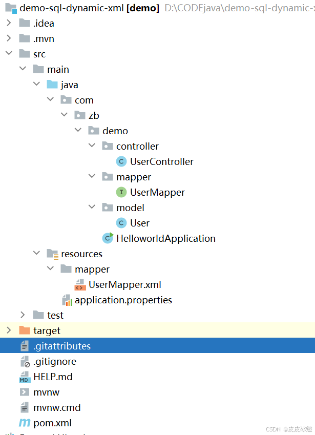
SpringBoot-17-MyBatis动态SQL标签之常用标签
文章目录 1 代码1.1 实体User.java1.2 接口UserMapper.java1.3 映射UserMapper.xml1.3.1 标签if1.3.2 标签if和where1.3.3 标签choose和when和otherwise1.4 UserController.java2 常用动态SQL标签2.1 标签set2.1.1 UserMapper.java2.1.2 UserMapper.xml2.1.3 UserController.ja…
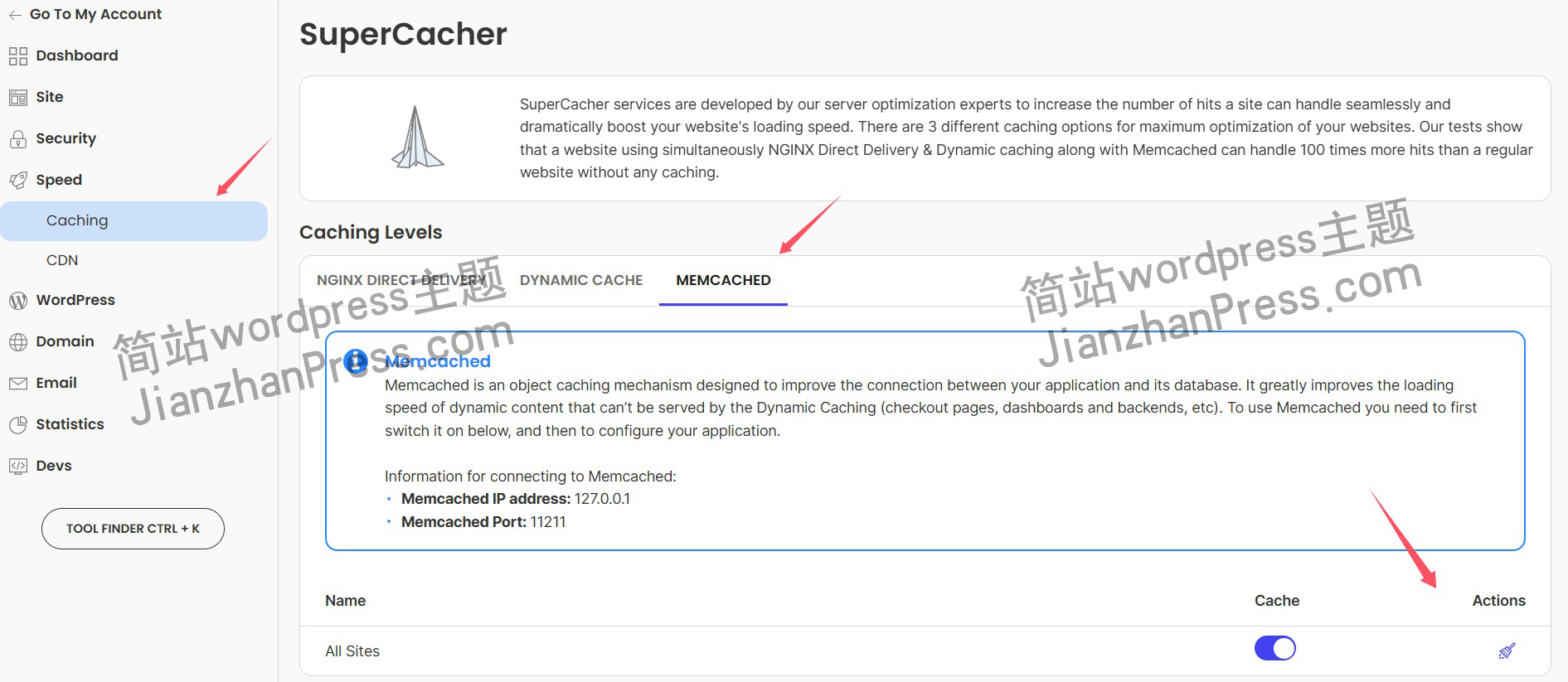
wordpress后台更新后 前端没变化的解决方法
使用siteground主机的wordpress网站,会出现更新了网站内容和修改了php模板文件、js文件、css文件、图片文件后,网站没有变化的情况。
不熟悉siteground主机的新手,遇到这个问题,就很抓狂,明明是哪都没操作错误&#x…
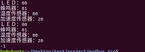
网络编程(Modbus进阶)
思维导图 Modbus RTU(先学一点理论)
概念 Modbus RTU 是工业自动化领域 最广泛应用的串行通信协议,由 Modicon 公司(现施耐德电气)于 1979 年推出。它以 高效率、强健性、易实现的特点成为工业控制系统的通信标准。 包…
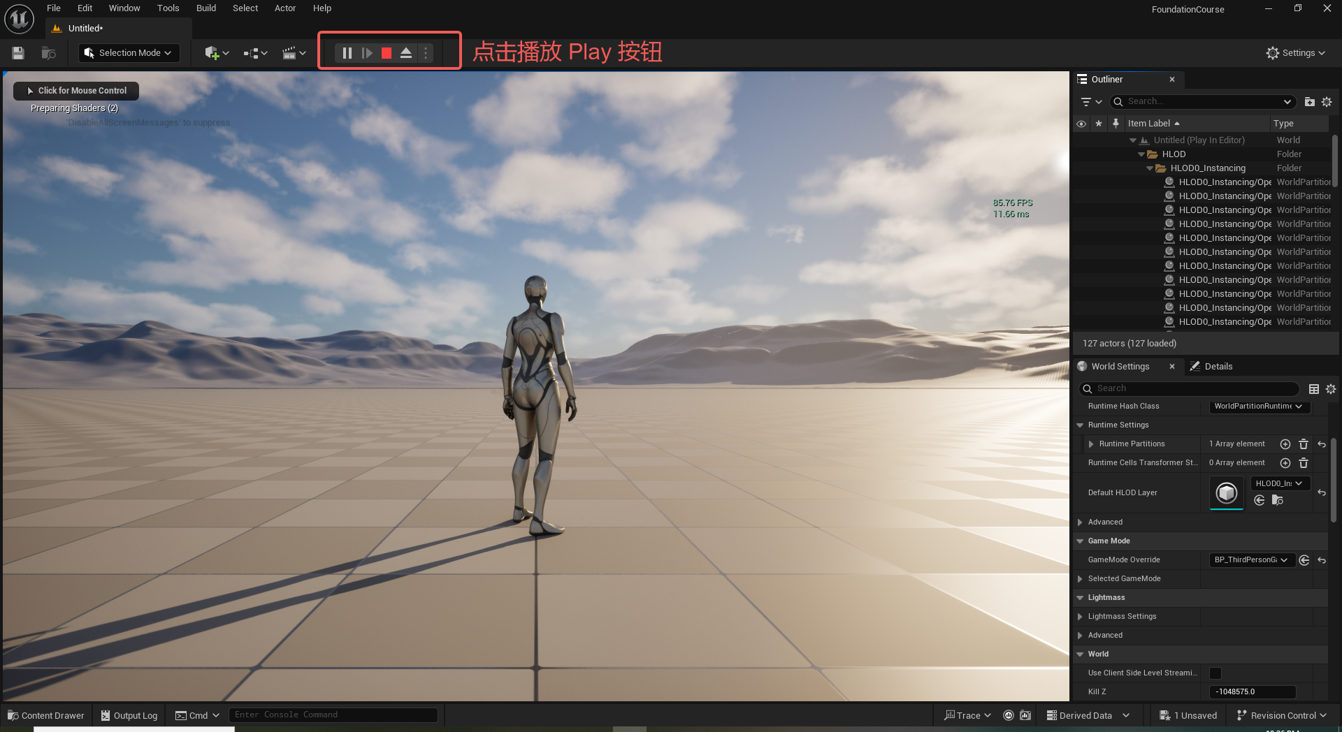
UE5 学习系列(二)用户操作界面及介绍
这篇博客是 UE5 学习系列博客的第二篇,在第一篇的基础上展开这篇内容。博客参考的 B 站视频资料和第一篇的链接如下:
【Note】:如果你已经完成安装等操作,可以只执行第一篇博客中 2. 新建一个空白游戏项目 章节操作,重…
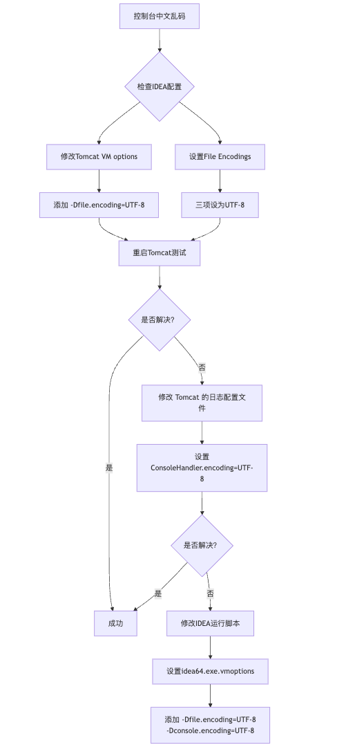
IDEA运行Tomcat出现乱码问题解决汇总
最近正值期末周,有很多同学在写期末Java web作业时,运行tomcat出现乱码问题,经过多次解决与研究,我做了如下整理:
原因:
IDEA本身编码与tomcat的编码与Windows编码不同导致,Windows 系统控制台…
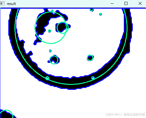
利用最小二乘法找圆心和半径
#include <iostream>
#include <vector>
#include <cmath>
#include <Eigen/Dense> // 需安装Eigen库用于矩阵运算 // 定义点结构
struct Point { double x, y; Point(double x_, double y_) : x(x_), y(y_) {}
}; // 最小二乘法求圆心和半径 …
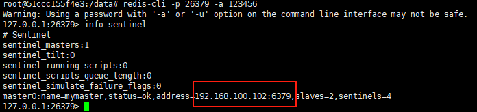
使用docker在3台服务器上搭建基于redis 6.x的一主两从三台均是哨兵模式
一、环境及版本说明
如果服务器已经安装了docker,则忽略此步骤,如果没有安装,则可以按照一下方式安装: 1. 在线安装(有互联网环境): 请看我这篇文章 传送阵>> 点我查看 2. 离线安装(内网环境):请看我这篇文章 传送阵>> 点我查看
说明:假设每台服务器已…
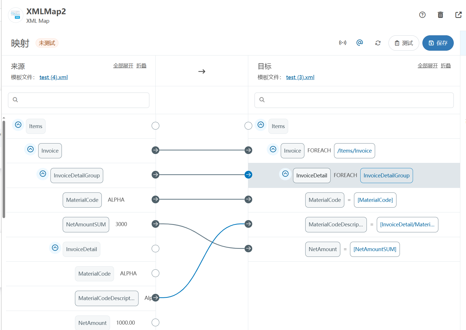
XML Group端口详解
在XML数据映射过程中,经常需要对数据进行分组聚合操作。例如,当处理包含多个物料明细的XML文件时,可能需要将相同物料号的明细归为一组,或对相同物料号的数量进行求和计算。传统实现方式通常需要编写脚本代码,增加了开…
LBE-LEX系列工业语音播放器|预警播报器|喇叭蜂鸣器的上位机配置操作说明
LBE-LEX系列工业语音播放器|预警播报器|喇叭蜂鸣器专为工业环境精心打造,完美适配AGV和无人叉车。同时,集成以太网与语音合成技术,为各类高级系统(如MES、调度系统、库位管理、立库等)提供高效便捷的语音交互体验。
L…
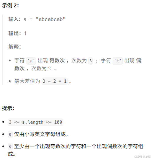
(LeetCode 每日一题) 3442. 奇偶频次间的最大差值 I (哈希、字符串)
题目:3442. 奇偶频次间的最大差值 I 思路 :哈希,时间复杂度0(n)。 用哈希表来记录每个字符串中字符的分布情况,哈希表这里用数组即可实现。
C版本:
class Solution {
public:int maxDifference(string s) {int a[26]…
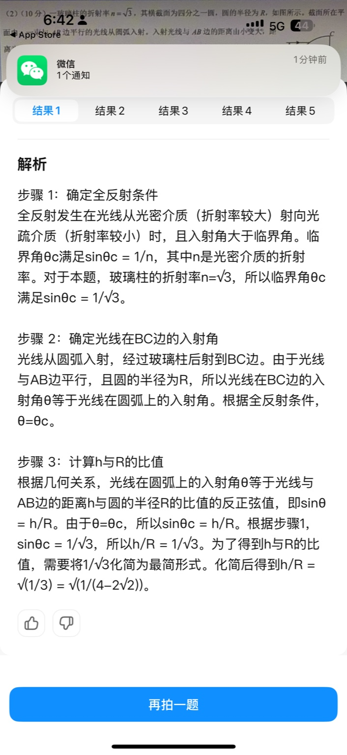
【大模型RAG】拍照搜题技术架构速览:三层管道、两级检索、兜底大模型
摘要
拍照搜题系统采用“三层管道(多模态 OCR → 语义检索 → 答案渲染)、两级检索(倒排 BM25 向量 HNSW)并以大语言模型兜底”的整体框架: 多模态 OCR 层 将题目图片经过超分、去噪、倾斜校正后,分别用…
【Axure高保真原型】引导弹窗
今天和大家中分享引导弹窗的原型模板,载入页面后,会显示引导弹窗,适用于引导用户使用页面,点击完成后,会显示下一个引导弹窗,直至最后一个引导弹窗完成后进入首页。具体效果可以点击下方视频观看或打开下方…
接口测试中缓存处理策略
在接口测试中,缓存处理策略是一个关键环节,直接影响测试结果的准确性和可靠性。合理的缓存处理策略能够确保测试环境的一致性,避免因缓存数据导致的测试偏差。以下是接口测试中常见的缓存处理策略及其详细说明:
一、缓存处理的核…
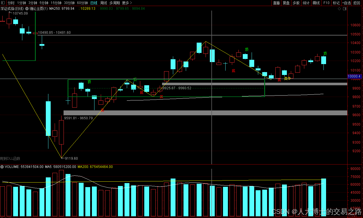
龙虎榜——20250610
上证指数放量收阴线,个股多数下跌,盘中受消息影响大幅波动。 深证指数放量收阴线形成顶分型,指数短线有调整的需求,大概需要一两天。 2025年6月10日龙虎榜行业方向分析 1. 金融科技
代表标的:御银股份、雄帝科技
驱动…
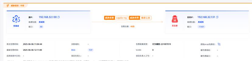
观成科技:隐蔽隧道工具Ligolo-ng加密流量分析
1.工具介绍
Ligolo-ng是一款由go编写的高效隧道工具,该工具基于TUN接口实现其功能,利用反向TCP/TLS连接建立一条隐蔽的通信信道,支持使用Let’s Encrypt自动生成证书。Ligolo-ng的通信隐蔽性体现在其支持多种连接方式,适应复杂网…
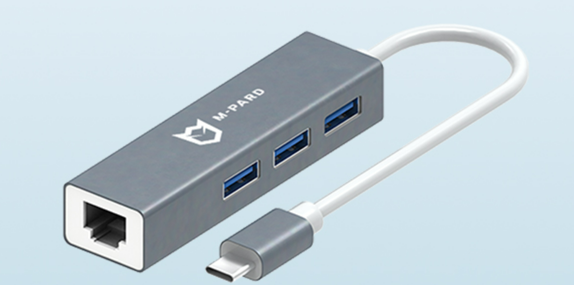
铭豹扩展坞 USB转网口 突然无法识别解决方法
当 USB 转网口扩展坞在一台笔记本上无法识别,但在其他电脑上正常工作时,问题通常出在笔记本自身或其与扩展坞的兼容性上。以下是系统化的定位思路和排查步骤,帮助你快速找到故障原因:
背景:
一个M-pard(铭豹)扩展坞的网卡突然无法识别了,扩展出来的三个USB接口正常。…
未来机器人的大脑:如何用神经网络模拟器实现更智能的决策?
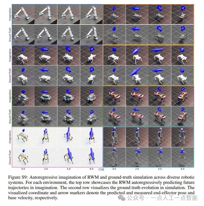
编辑:陈萍萍的公主一点人工一点智能 未来机器人的大脑:如何用神经网络模拟器实现更智能的决策?RWM通过双自回归机制有效解决了复合误差、部分可观测性和随机动力学等关键挑战,在不依赖领域特定归纳偏见的条件下实现了卓越的预测准…
Linux应用开发之网络套接字编程(实例篇)
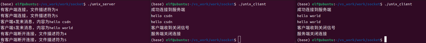
服务端与客户端单连接
服务端代码
#include <sys/socket.h>
#include <sys/types.h>
#include <netinet/in.h>
#include <stdio.h>
#include <stdlib.h>
#include <string.h>
#include <arpa/inet.h>
#include <pthread.h>
…

华为云AI开发平台ModelArts
华为云ModelArts:重塑AI开发流程的“智能引擎”与“创新加速器”!
在人工智能浪潮席卷全球的2025年,企业拥抱AI的意愿空前高涨,但技术门槛高、流程复杂、资源投入巨大的现实,却让许多创新构想止步于实验室。数据科学家…
深度学习在微纳光子学中的应用
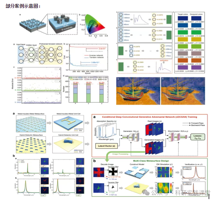
深度学习在微纳光子学中的主要应用方向
深度学习与微纳光子学的结合主要集中在以下几个方向:
逆向设计 通过神经网络快速预测微纳结构的光学响应,替代传统耗时的数值模拟方法。例如设计超表面、光子晶体等结构。
特征提取与优化 从复杂的光学数据中自…