Normal Mapping
又到了介绍法线贴图的地方,我感觉我已经写了很多遍了...
法线贴图用最简单的话来介绍的话,就是通过修改贴图对应物体表面的法线来修改光照效果,从而在不修改物体实际几何形状的前提下实现不同于物体几何形状的视觉效果。
因此对于法线贴图来说,最重要的内容就是去修改法线贴图对于物体表面的法线。
  vec3 normal = texture(normalMap, TexCoords).rgb;
  normal = normalize(normal * 2.0 - 1.0);
  normal = normalize(TBN * normal);
这是我们在物体的片元着色器实现的内容,就是根据法线贴图的内容更换法线。
在这里我们不妨回顾一下法线贴图的原理:
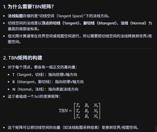
法线贴图的“蓝色”就代表“正对表面外”,红色/绿色代表“沿U/V方向偏转”,整个流程无非就是:法线贴图以RGB值来记录对法线方向的干扰,这个干扰是在切线空间中进行的,我们还需要TBN矩阵——这个工具来将变换后的法线映射回世界坐标系中。
效果如图:
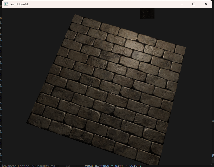
看起来确实有凹凸不平的质感——但其实,这只是薄薄的一个平面生成的效果。
Parallax Mapping
视差贴图和法线贴图类似也是也是不改变物体实际几何形状的前提下去修改视觉效果,可是和法线贴图直接去修改法线方向不同,视差贴图通过动态偏移纹理坐标实现高度不同的视觉效果。
vec2 ParallaxMapping(vec2 texCoords, vec3 viewDir)
{
    float height =  texture(depthMap, texCoords).r;
    return texCoords - viewDir.xy * (height * heightScale);
}

void main()
{
    // offset texture coordinates with Parallax Mapping
    vec3 viewDir = normalize(fs_in.TangentViewPos - fs_in.TangentFragPos);
    vec2 texCoords = fs_in.TexCoords;

    texCoords = ParallaxMapping(fs_in.TexCoords,  viewDir);
    if(texCoords.x > 1.0 || texCoords.y > 1.0 || texCoords.x < 0.0 || texCoords.y < 0.0)
        discard;

    // obtain normal from normal map
    vec3 normal = texture(normalMap, texCoords).rgb;
    normal = normalize(normal * 2.0 - 1.0);

    // get diffuse color
    vec3 color = texture(diffuseMap, texCoords).rgb;
    // ambient
    vec3 ambient = 0.1 * color;
    // diffuse
    vec3 lightDir = normalize(fs_in.TangentLightPos - fs_in.TangentFragPos);
    float diff = max(dot(lightDir, normal), 0.0);
    vec3 diffuse = diff * color;
    // specular
    vec3 reflectDir = reflect(-lightDir, normal);
    vec3 halfwayDir = normalize(lightDir + viewDir);
    float spec = pow(max(dot(normal, halfwayDir), 0.0), 32.0);

    vec3 specular = vec3(0.2) * spec;
    FragColor = vec4(ambient + diffuse + specular, 1.0);
}
可以看到我们的视差贴图会根据深度贴图的R值来修改原来纹理坐标,在片元着色器的执行流程中,我们的纹理会根据视线方向来动态地调整根据深度贴图的R值修改过的纹理坐标,从而达到视觉落差的效果。
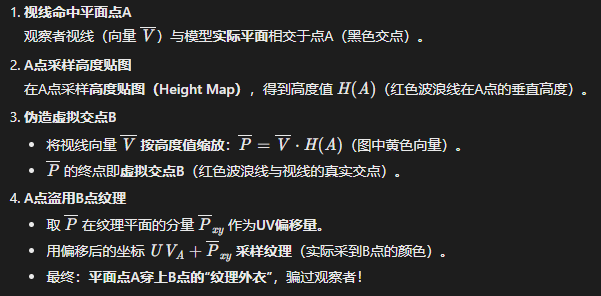
说起来当然很简单,但是其背后的工作原理呢?
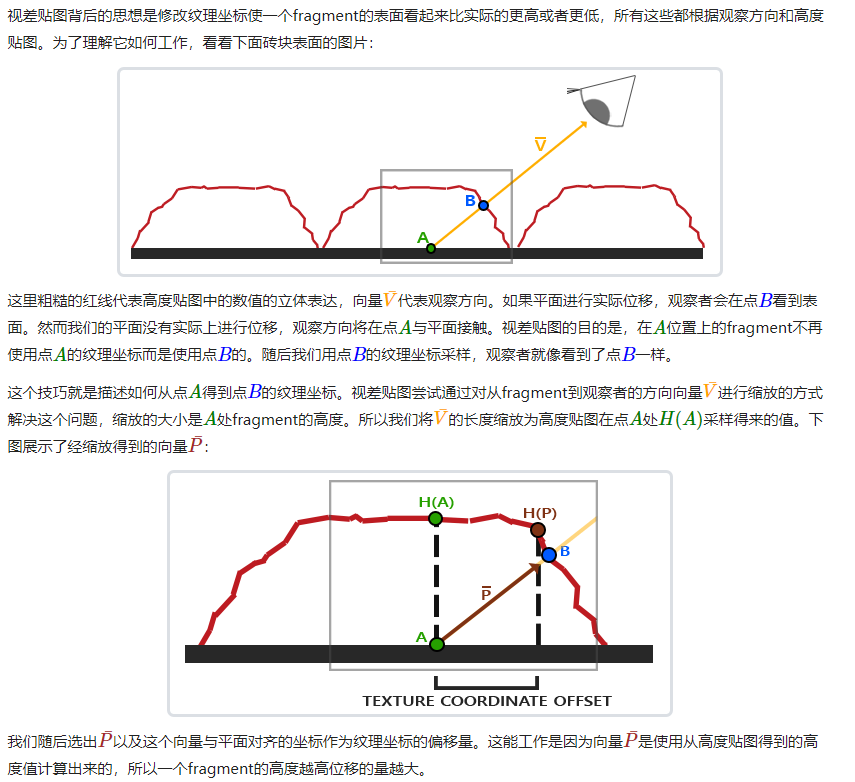
移花接木,狸猫换太子,卧槽这个视差贴图怎么这么坏啊。 用比较简单的话来说就是:首先我们的视线看向这个片元时,视线真正与物体表面的交点在A点,但是我们在A点的着色渲染成B点的颜色的话,不就实现了纹理坐标的偏移,从而实现视觉落差的效果了。这个B点是怎么得到的呢?就是根据我们的视差贴图修改该片元的高度值后与视线相交得到的。
陡峭视差映射(Steep Parallax Mapping)是视差映射的扩展,原则是一样的,但不是使用一个样本而是多个样本来确定向量。即使在陡峭的高度变化的情况下,它也能得到更好的结果,原因在于该技术通过增加采样的数量提高了精确性。
陡峭视差映射的基本思想是将总深度范围划分为同一个深度/高度的多个层。从每个层中我们沿着向量方向移动采样纹理坐标,直到我们找到一个采样低于当前层的深度值。
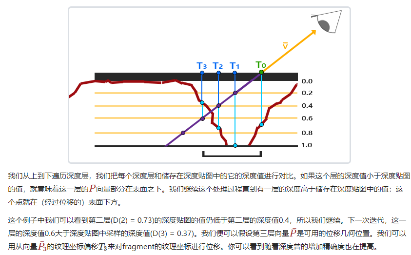
其实就是我们多很多个深度层,然后将视线和这些深度层的交点与深度贴图的深度值一一比较,找到第一个符合深度贴图的深度大于交点深度值的深度层,把这个深度层与视线的交点对于的深度值作为我们的纹理颜色渲染对象即可。
代码上这样改动:
vec2 ParallaxMapping(vec2 texCoords, vec3 viewDir)
{
// number of depth layers
const float minLayers = 8;
const float maxLayers = 32;
float numLayers = mix(maxLayers, minLayers, abs(dot(vec3(0.0, 0.0, 1.0), viewDir)));
// calculate the size of each layer
float layerDepth = 1.0 / numLayers;
// depth of current layer
float currentLayerDepth = 0.0;
// the amount to shift the texture coordinates per layer (from vector P)
vec2 P = viewDir.xy / viewDir.z * heightScale;
vec2 deltaTexCoords = P / numLayers;
// get initial values
vec2 currentTexCoords = texCoords;
float currentDepthMapValue = texture(depthMap, currentTexCoords).r;
while(currentLayerDepth < currentDepthMapValue)
{
// shift texture coordinates along direction of P
currentTexCoords -= deltaTexCoords;
// get depthmap value at current texture coordinates
currentDepthMapValue = texture(depthMap, currentTexCoords).r;
// get depth of next layer
currentLayerDepth += layerDepth;
}
return currentTexCoords;
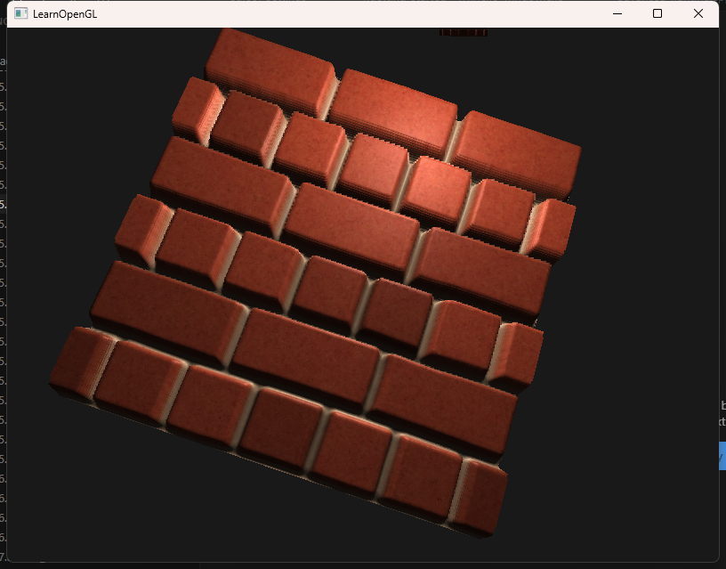
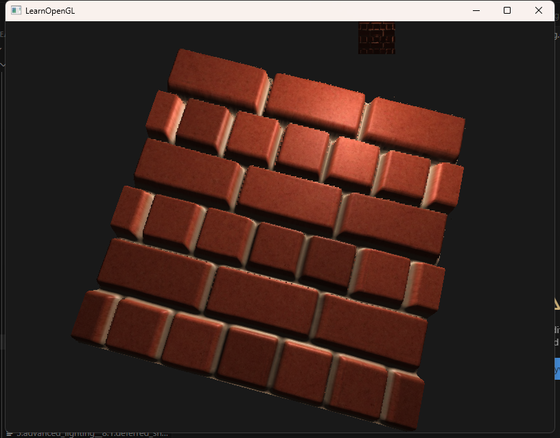
}效果如图:
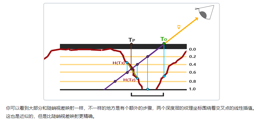
在这个基础上可以实现效果更好的视差遮蔽映射(Parallax Occlusion Mapping),只需要多加一个线性插值的操作即可。
vec2 ParallaxMapping(vec2 texCoords, vec3 viewDir)
{
// number of depth layers
const float minLayers = 8;
const float maxLayers = 32;
float numLayers = mix(maxLayers, minLayers, abs(dot(vec3(0.0, 0.0, 1.0), viewDir)));
// calculate the size of each layer
float layerDepth = 1.0 / numLayers;
// depth of current layer
float currentLayerDepth = 0.0;
// the amount to shift the texture coordinates per layer (from vector P)
vec2 P = viewDir.xy / viewDir.z * heightScale;
vec2 deltaTexCoords = P / numLayers;
// get initial values
vec2 currentTexCoords = texCoords;
float currentDepthMapValue = texture(depthMap, currentTexCoords).r;
while(currentLayerDepth < currentDepthMapValue)
{
// shift texture coordinates along direction of P
currentTexCoords -= deltaTexCoords;
// get depthmap value at current texture coordinates
currentDepthMapValue = texture(depthMap, currentTexCoords).r;
// get depth of next layer
currentLayerDepth += layerDepth;
}
// get texture coordinates before collision (reverse operations)
vec2 prevTexCoords = currentTexCoords + deltaTexCoords;
// get depth after and before collision for linear interpolation
float afterDepth = currentDepthMapValue - currentLayerDepth;
float beforeDepth = texture(depthMap, prevTexCoords).r - currentLayerDepth + layerDepth;
// interpolation of texture coordinates
float weight = afterDepth / (afterDepth - beforeDepth);
vec2 finalTexCoords = prevTexCoords * weight + currentTexCoords * (1.0 - weight);
return finalTexCoords;
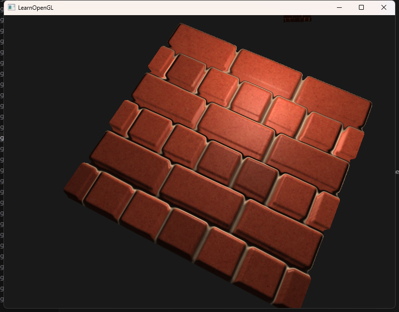
}效果如图:
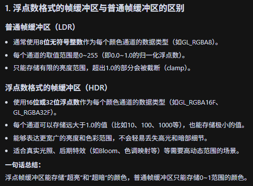
HDR
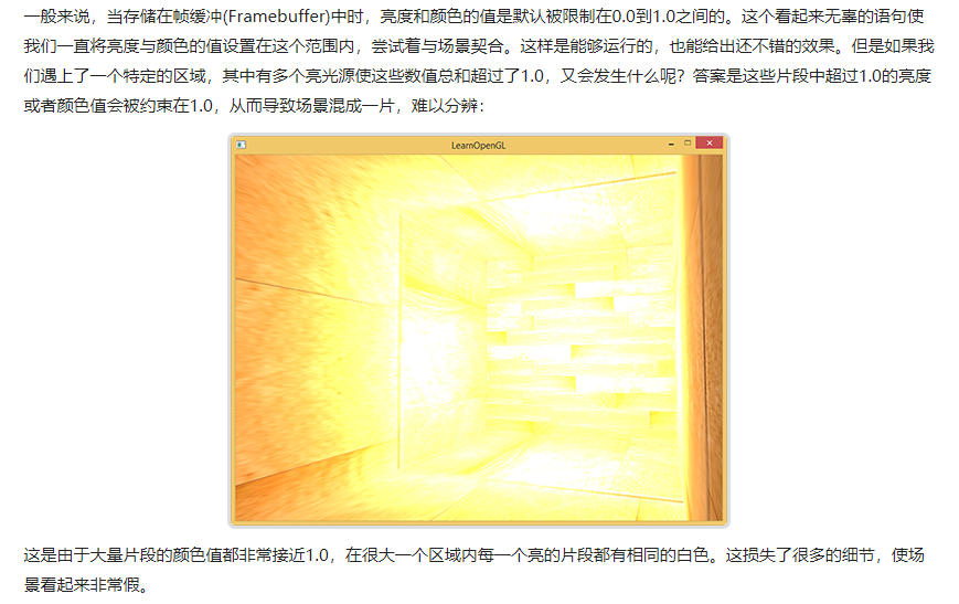
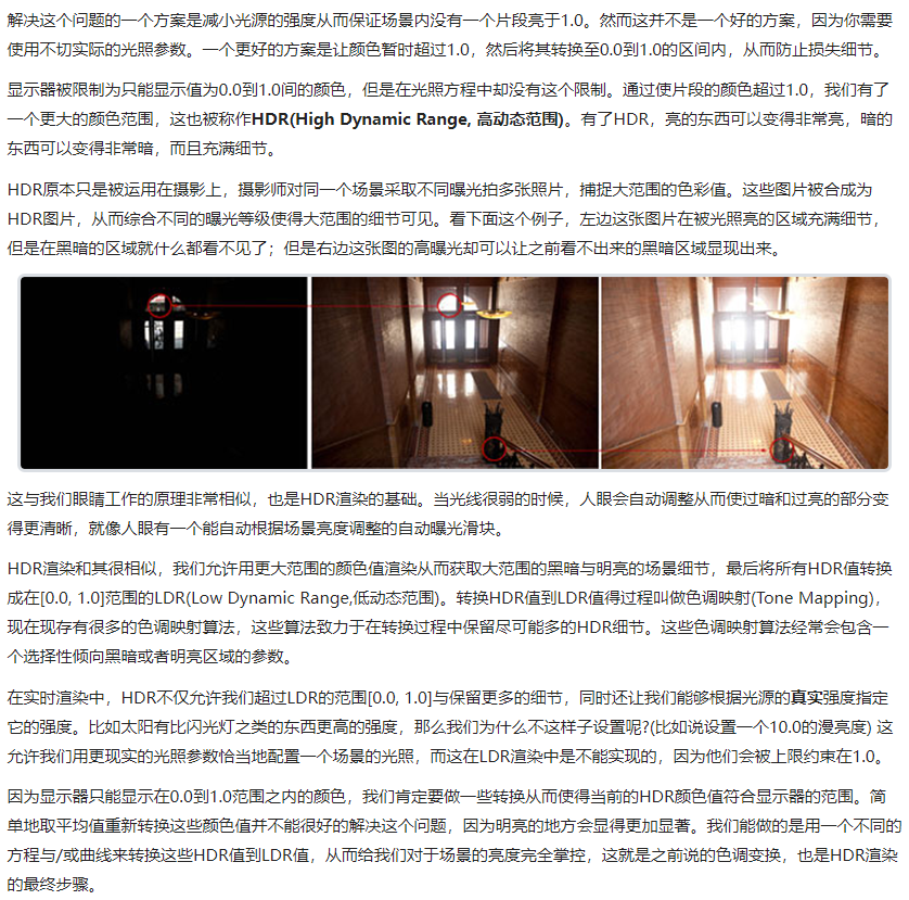
上来都是一些介绍HDR高动态范围概念的文字,我觉得这个翻译实在废话有点多,说白了HDR就是解决摄像设备里人为设置的亮度范围导致的过亮或者过暗时丢失的细节的机制:它允许你短暂地突破这个亮度范围,在捕获到细节后再将这些带有细节的图像融合在一起之后调整亮度到范围内。
很好,明白原理之后让我们深入细节。
首先我们需要一个浮点数类型的帧缓冲:
// 创建浮点帧缓冲
unsigned int hdrFBO;
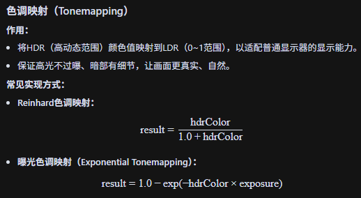
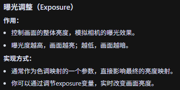
glGenFramebuffers(1, &hdrFBO);然后我们还涉及到色调映射(Tonemapping)和曝光调整(Exposure)。
// 2. now render floating point color buffer to 2D quad and tonemap HDR colors to default framebuffer's (clamped) color range
hdrShader.use();
glActiveTexture(GL_TEXTURE0);
glBindTexture(GL_TEXTURE_2D, colorBuffer);
hdrShader.setInt("hdr", hdr);
hdrShader.setFloat("exposure", exposure);
renderQuad();
#version 330 core
out vec4 FragColor;
in vec2 TexCoords;
uniform sampler2D hdrBuffer; // HDR帧缓冲的颜色纹理
uniform bool hdr; // 是否启用HDR色调映射
uniform float exposure; // 曝光度
void main()
{
const float gamma = 2.2;
vec3 hdrColor = texture(hdrBuffer, TexCoords).rgb; // 采样HDR颜色
if(hdr)
{
// Reinhard色调映射(被注释掉了)
// vec3 result = hdrColor / (hdrColor + vec3(1.0));
// 曝光色调映射
vec3 result = vec3(1.0) - exp(-hdrColor * exposure);
// Gamma校正
result = pow(result, vec3(1.0 / gamma));
FragColor = vec4(result, 1.0);
}
else
{
// 只做Gamma校正,不做色调映射
vec3 result = pow(hdrColor, vec3(1.0 / gamma));
FragColor = vec4(result, 1.0);
}
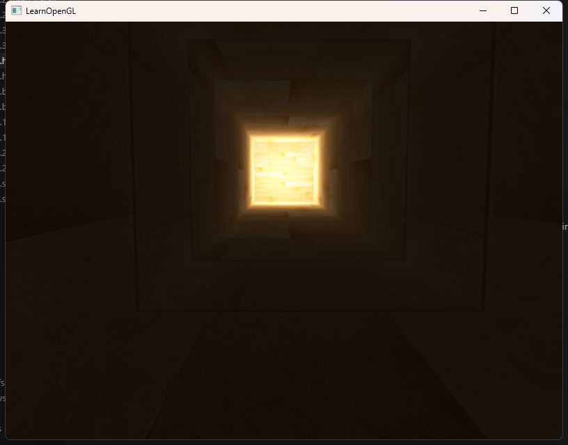
}效果如图: