书接上文
《单片机开发—ESP32-S3模块上手》
《单片机开发—ESP32S3移植lvgl+触摸屏》
参考内容
依旧是参考韦东山老师的作品来移植的
《ESP32|爷青回!ESP32(单片机) NES模拟器_NES游戏机掌机教程(开源+详细讲解实现代码!)》
韦老师已经将代码开源,喜欢的朋友当然是可以去支持一波。

另外还有github上的一份原始代码,喜欢从头来的,也可以去学习一下,核心部分是一样的,适配硬件的部分需要自己来修改。
github上的espressif/esp32-nesemu
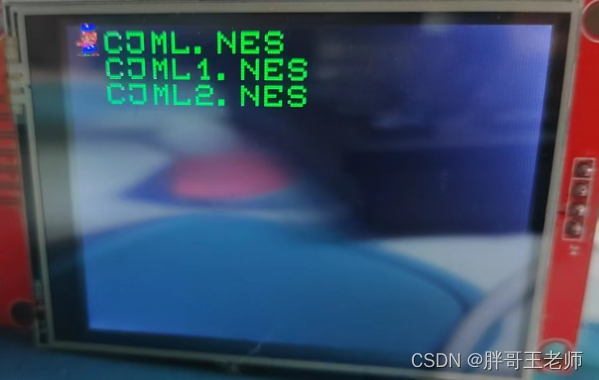
移植效果
esp32s3模拟nes
小时候玩的第一个游戏就是超级玛丽,算是callback了。

移植过程
我使用的是ESP-IDF4.4的开发环境,和韦老师的不太一样,并且硬件也是ESP32S3,所以我的方法就是将代码移植过来,重新构建了一个工程。
源码

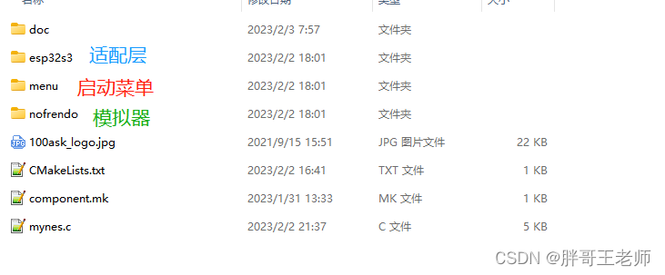
将menu和nofrendo代码复制过来,并且将适配层代码提出来并列目录。工程采用了原始的helloworld项目,只是重新修改了主函数的c文件。
漫长的编译过程
修改Cmake
首先需要添加对目录的检索,将c文件都进行编译,并且添加头文件检索路径,以便包含的时候,更加简单。
FILE(GLOB_RECURSE app_sources ./*.* ./menu/*.* ./esp32s3/*.* ./nofrendo/*.* ./nofrendo/cpu/*.* ./nofrendo/libsnss/*.* ./nofrendo/mappers/*.* ./nofrendo/nes/*.* ./nofrendo/sndhrdw/*.*)

idf_component_register(
 SRCS ${app_sources}
 INCLUDE_DIRS "."
 INCLUDE_DIRS "./menu/"
 INCLUDE_DIRS "./esp32s3/"
 INCLUDE_DIRS "./nofrendo/"
 INCLUDE_DIRS "./nofrendo/cpu/"
 INCLUDE_DIRS "./nofrendo/libsnss/"
 INCLUDE_DIRS "./nofrendo/mappers/"
 INCLUDE_DIRS "./nofrendo/nes/"
 INCLUDE_DIRS "./nofrendo/sndhrdw/"
 EMBED_FILES "./100ask_logo.jpg"
 )
这两行就达到了自动搜索对应路径的c文件,并且检索对应路径的头文件。
另外如果编译的时候,需要修改一些FLAGS或者增加一些宏定义进行配置编译,参考下面句子修改
set(CMAKE_C_FLAGS "${CMAKE_C_FLAGS} -Wno-error=char-subscripts -Wno-error=attributes -DNOFRENDO_DEBUG -DCONFIG_HW_CONTROLLER_GPIO")
set(CMAKE_CXX_FLAGS "${CMAKE_CXX_FLAGS} -Wno-error=char-subscripts -Wno-error=attributes -DNOFRENDO_DEBUG -DCONFIG_HW_CONTROLLER_GPIO")
我将对应韦老师的代码中定义的宏定义以及FLAGS放在这里了,然后才能开始第一步的编译。否则就怕有其他莫名其妙的问题。

宏定义与函数冲突
编译的时候遇到
expected declaration specifiers or '...' before '
原因就是模拟器中重新定义了malloc和free
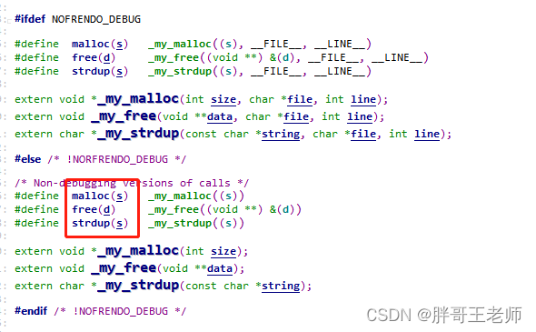
但是和其他文件一起编译的时候,收到stdlib.h中的同名函数影响,就会报错。
尝试过用原有的malloc,但是会出现内存异常。

所以直接将模拟器部分的代码,重新替换了新的宏定义,
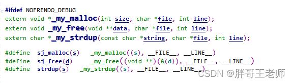
里面可能有一些问题,通过这个重新封装的函数,在释放空指针等操作的时候,给出提示,或者直接跳过。
不起作用的一句话
error: this 'if' clause does not guard... [-Werror=misleading-indentation]
报错的
if (!pMem)
    return XX;
修改后
if (!pMem)
{
    return XX;
}
反正我是一直看不上那些不爱加括号的代码。一块的功能,就是要用括号括起来,这样看起来工整多了。

移植小窍门
涉及到硬件的部分,首先把中间层的代码中,每个文件对外的接口提供出来,保证函数存在,该有返回值的,有返回值,其余代码注释掉。
保证编译通过,然后烧写,根据报错的内容,一步一步打开代码再修改,这样能够熟悉所有的流程,并且学习出代码的功能。
随后慢慢增加代码。

移植过程
该注释的注释掉,很快就能编译通过。然后就开始调试。
SD卡模块
源码首先是注册SD卡

因为是要将nes的rom放在sd卡中。
参考esp32s3的example代码。替换掉源码中的部分代码
esp_err_t init_sd_card(void)
{
	esp_err_t ret;

	// Options for mounting the filesystem.
	// If format_if_mount_failed is set to true, SD card will be partitioned and
	// formatted in case when mounting fails.
	esp_vfs_fat_sdmmc_mount_config_t mount_config = {
#ifdef CONFIG_EXAMPLE_FORMAT_IF_MOUNT_FAILED
		.format_if_mount_failed = true,
#else
		.format_if_mount_failed = false,
#endif // EXAMPLE_FORMAT_IF_MOUNT_FAILED
		.max_files = 5,
		.allocation_unit_size = 16 * 1024
	};
	sdmmc_card_t *card;
	const char mount_point[] = "/sdcard";
	ESP_LOGI(TAG, "Initializing SD card");

	// Use settings defined above to initialize SD card and mount FAT filesystem.
	// Note: esp_vfs_fat_sdmmc/sdspi_mount is all-in-one convenience functions.
	// Please check its source code and implement error recovery when developing
	// production applications.
	ESP_LOGI(TAG, "Using SPI peripheral");

	sdmmc_host_t host = SDSPI_HOST_DEFAULT();
	host.slot=SD_HOST;

	spi_bus_config_t bus_cfg = {
		.mosi_io_num = SD_MOSI,
		.miso_io_num = SD_MISO,
		.sclk_io_num = SD_CLK,
		.quadwp_io_num = -1,
		.quadhd_io_num = -1,
		.max_transfer_sz = 4000,
	};
	ret = spi_bus_initialize(host.slot, &bus_cfg, SPI_DMA_CH_AUTO);
	if (ret != ESP_OK) {
		ESP_LOGE(TAG, "Failed to initialize bus.");
		return;
	}

	// This initializes the slot without card detect (CD) and write protect (WP) signals.
	// Modify slot_config.gpio_cd and slot_config.gpio_wp if your board has these signals.
	sdspi_device_config_t slot_config = SDSPI_DEVICE_CONFIG_DEFAULT();
	slot_config.gpio_cs = SD_CS;
	slot_config.host_id = host.slot;

	ESP_LOGI(TAG, "Mounting filesystem");
	ret = esp_vfs_fat_sdspi_mount(mount_point, &host, &slot_config, &mount_config, &card);

	if (ret != ESP_OK)
	{
		if (ret == ESP_FAIL)
		{
			ESP_LOGE(TAG, "Failed to mount filesystem. "
					 "If you want the card to be formatted, set the CONFIG_EXAMPLE_FORMAT_IF_MOUNT_FAILED menuconfig option.");
		}
		else
		{
			ESP_LOGE(TAG, "Failed to initialize the card (%s). "
					 "Make sure SD card lines have pull-up resistors in place.", esp_err_to_name(ret));
		}
		return ret;
	}
	else
	{
		// Card has been initialized, print its properties
		sdmmc_card_print_info(stdout, card);
		return ESP_OK;
	}

}
这里注意SD的SPI通道选择,因为LCD通常用高速通道,所以这个SD卡我们用在了SPI3上。
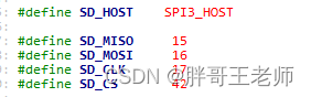
一共就两个SPI,只能这样计划了。

输入模块
源码第二步就是输入设备初始化

这里的输入设备支持到了三种,包括GPIO,I2C和手柄。
这里根据不同宏定义进行了编译包含,后者我们都没有,所以只能用GPIO。
上拉和下拉的选择
这里我用的是一个GPIO按键模块,前面在w801上用过的。
输入方式下。内部上拉保证了如果没有输入,就是高电平,下拉相反,没有输入就是低电平。
由于我这里公共端是高电平,所以需要使能下拉,保证了:
无输入:0,有输入:1
static void _init_gpio(gpio_num_t gpio_num)
{
    gpio_config_t io_conf = {};

    io_conf.intr_type = GPIO_INTR_POSEDGE;
    io_conf.pin_bit_mask = (1ULL<<gpio_num);
    io_conf.mode = GPIO_MODE_INPUT;
    io_conf.pull_up_en = 0;
    io_conf.pull_down_en = 1;
    gpio_config(&io_conf);
}
然后定义了部分GPIO来使用
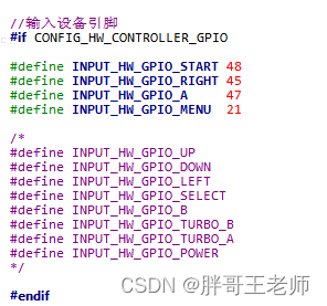
只是为了验证部分功能,所以只注册了部分按键

显示模块
第三步就是显示菜单,然后结合前面的内容选择rom

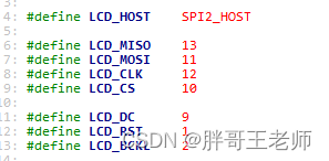
这里的初始化与esp32s3基本一致,所以修改好对应的引脚和SPI通道,就可以使用了
然后需要修改一下这个函数
//Load Rom list from flash partition to char array(lines), init some variables for printing rom list
void initRomList()
{
	DIR *pDir = NULL;
	struct dirent * pEnt = NULL;
	pDir = opendir("/sdcard/nes");
	char fileName[FILENAME_LENGTH][FILENAME_LENGTH+1];
	int dir_count = 0;

	entryCount = 0;


	if (NULL == pDir)
	{
		perror("opendir");
	}
	else
	{
		while (1)
		{
			pEnt = readdir(pDir);
			if(pEnt != NULL)
			{
				ESP_LOGI(TAG,"rom name[%s]", pEnt->d_name);
				strcpy(fileName[dir_count], pEnt->d_name);
				dir_count++;
				entryCount++;
			}
			else
			{
				break;
			}
		}
		closedir(pDir);
	}
	if(entryCount > 0)
	{
		menuEntries = (MenuEntry *)malloc(entryCount * sizeof(MenuEntry));
		for (int i = 0; i < entryCount; i++)
		{
			//menuEntries[i].entryNumber = i;
			//menuEntries[i].icon = 'E';
			menuEntries[i].icon = '$';

			//strcpy(menuEntries[i].name, fileName[i]);
			memset(menuEntries[i].fileName,0,FILENAME_LENGTH+1);//sunjin
			strcpy(menuEntries[i].fileName, fileName[i]);

			for (int j = strlen(menuEntries[i].fileName); j > 0; j--)
			{
				if (menuEntries[i].fileName[j] < ' ')
				{
					menuEntries[i].fileName[j] = '\0';
				}
			}
		}
		ESP_LOGI(TAG,"Read %d rom entries", entryCount);
	}
	else
	{
		ESP_LOGW(TAG,"no roms!");
	}
}
里面我修改了一下获取的文件数量变量初始值以及初始化了一下数组,否则会出现内存异常以及显示乱码的问题。

到达这一步的时候,就可以显示开机动画以及rom选择菜单了。
读取ROM
接下来就是正式启动模拟器了

这里的需要修改的,就是将rom文件读取到内存中,源码为这个函数

这里涉及到了一个分区表的概念,具体可以参考
分区表
简单来说就是将数据从SD卡读取到FALSH中,然后就可以当成一个静态数组来使用,访问这里就像访问内存一样,解决了单片机内存小的问题。
这里我就不一样了,我有8M的内存,所以这里我直接修改放在内存中。

	char *romdata;

	// Open the file
	ESP_LOGI(TAG, "Reading rom from %s", selectedRomFilename);
	FILE *rom = fopen(selectedRomFilename, "r");
	long fileSize = -1;
	if (!rom)
	{
		ESP_LOGE(TAG, "Could not read %s", selectedRomFilename);
		exit(1);
	}

	// First figure out how large the file is
	fseek(rom, 0L, SEEK_END);
	fileSize = ftell(rom);

	rewind(rom);
	romdata=malloc(fileSize+READ_BUFFER_SIZE);
	if (!romdata)
	{
		ESP_LOGE(TAG, "Could not malloc ");
		exit(1);
	}

	// Copy the file contents into EEPROM memory
	char buffer[READ_BUFFER_SIZE];
	int offset = 0;
	while (fread(buffer, 1, READ_BUFFER_SIZE, rom) > 0)
	{
		memcpy(romdata+offset,buffer,READ_BUFFER_SIZE);
		offset += READ_BUFFER_SIZE;
	}
	fclose(rom);

	ESP_LOGI(TAG, "Loaded %d bytes into ROM memory", offset);

	return (char *)romdata;
就是豪横。
绘制游戏
spi_lcd.c中对外就提供了两个接口,
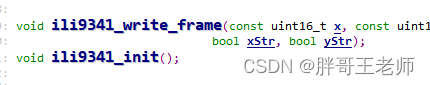
其实就是用来初始化显示屏和绘制图像的,韦老师的代码中用额的gpio模拟的方式进行驱动屏幕,与前面显示菜单用了两套软件。

这里我整合为一套,就用了显示菜单的方式。所以初始化中,我只保留了一些变量初始化,然后申请了2条缓存,用来更新画面
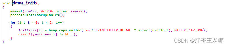
绘制图像的函数,就比较难了。我看了好久才找到显示的数据。
void draw_write_frame(const uint16_t xs, const uint16_t ys, const uint16_t width, const uint16_t height, const uint8_t *data[],		bool xStr, bool yStr)
{
	int x, y;
	int xx, yy;
	int i;
	uint16_t x1, y1, evenPixel, oddPixel, backgroundColor;
	int drsy = 0;

	uint32_t xv, yv, dc;
	uint32_t temp[16];

	if(data==NULL)
	{
		return;
	}
	if (getShowMenu() != lastShowMenu)
	{
		memset(rowCrc, 0, sizeof rowCrc);
	}
	lastShowMenu = getShowMenu();

	int lastY = -1;
	int lastYshown = 0;

	// Black background
	backgroundColor = 0;

	for (y = 0; y < height; y++)
	{
		yy = yStr ? scaleY[y] : y;
		if (lastY == yy)
		{
			if (!lastYshown && !getShowMenu())
				continue;
		}
		else
		{
			lastY = yy;
			uint16_t crc = calcCrc(data[yy]);
			if (crc == rowCrc[yy] && !getShowMenu())
			{
				lastYshown = false;
				continue;
			}
			else
			{
				lastYshown = true;
				rowCrc[yy] = crc;
			}
		}

		//start line
		x1 = xs + (width - 1);
		y1 = ys + y + (height - 1);

		xv = U16x2toU32(xs, x1);
		yv = U16x2toU32((ys + y), y1);

		drsy = 0;

		x = 0;
		while (x < width)
		{
			// Render 32 pixels, grouped as pairs of 16-bit pixels stored in 32-bit values
			for (i = 0; i < 16; i++)
			{
				xx = xStr ? scaleX[x] : x;
				if (xx >= 32 && !xStr)
					xx -= 32;
				evenPixel = myPalette[(unsigned char)(data[yy][xx])];
				x++;

				xx = xStr ? scaleX[x] : x;
				if (xx >= 32 && !xStr)
					xx -= 32;
				oddPixel = myPalette[(unsigned char)(data[yy][xx])];
				x++;

				if (!xStr && (x <= 32 || x >= 288))
					evenPixel = oddPixel = backgroundColor;
				if (!yStr && y >= 224)
					evenPixel = oddPixel = backgroundColor;
				if (getShowMenu())
				{
					evenPixel = oddPixel = renderInGameMenu(x, y, evenPixel, oddPixel, xStr, yStr);
				}
				fastlines[BbufIdx][drsy++]=evenPixel;
				fastlines[BbufIdx][drsy++]=oddPixel;
			}
		}
		AbufIdx = BbufIdx;
		BbufIdx = 1 - BbufIdx;

		nes_100ask_send_line_finish(mylcd_spi);
		nes_100ask_send_one_line(mylcd_spi, yy, (uint16_t*)(fastlines[AbufIdx]));

	}

	if (nes_100ask_get_shutdown())
		setBrightness(nes_100ask_get_bright());
//#if LCD_BCKL >= 0
//	if (nes_100ask_get_bright() == -1)
//		LCD_BKG_OFF();
//#endif

}
这里有两个问题。
- 数据获取
一开是以为传入的data就是数据,其实后来发现,这里需要计算出每个像素,
				fastlines[BbufIdx][drsy++]=evenPixel;
				fastlines[BbufIdx][drsy++]=oddPixel;
再将循环buf一次一次交替行绘制。
- 调色板
模拟器计算出每个点的颜色,结果绘制来发现,颜色不对,像极了我之前在w801上移植的时候,于是我返回去找了一下,原来是这个原因,在写入SPI总线 时候,大小端的问题,所以为了从根本上解决问题。
我直接修改了调色板!
uint16 myPalette[256];

unsigned short Convert(unsigned short s)
{
	char right, left;
	right = s& 0XFF;//低八位
	left = s >> 8;//高八位  右移8位
	s = right * 256 + left;
	return s;
}

static void set_palette(rgb_t *pal)
{
	uint16 c;

	int i;

	for (i = 0; i < 256; i++)
	{
		c = (pal[i].b >> 3) + ((pal[i].g >> 2) << 5) + ((pal[i].r >> 3) << 11);
		myPalette[i] = Convert(c);
	}
}
因为不要在画图的时候再进行转化,会影响显示速度。

其他功能
剩余的问题包括了声音,手柄2的扩展,这些东西后面需要补充一下,才能像一个能用的游戏机。
所以还有续集。
结束语
以前人有两个坎,73和84,现在人也有两坎,35和65,薅羊毛也不能光可着这一代人薅吧。