一.GPIO简介
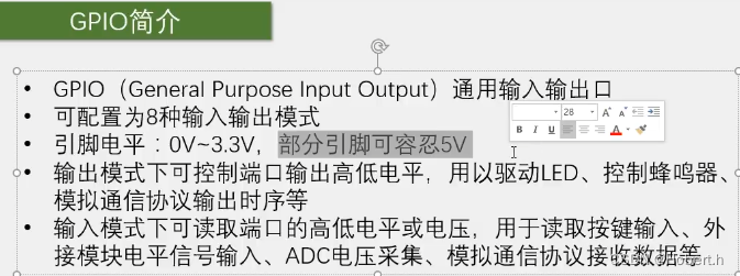
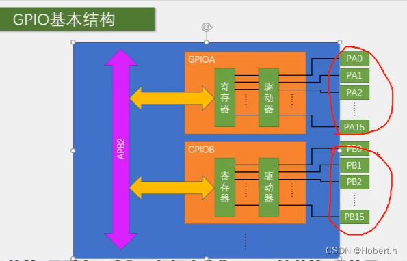
所有的GPIO都挂载到APB2上,每个GPIO有16个引脚
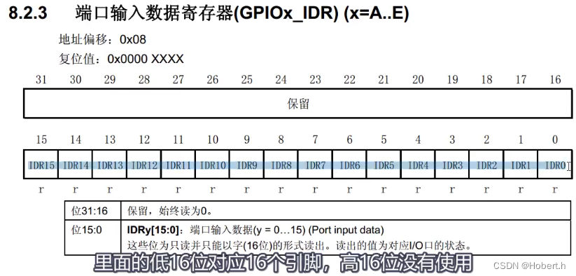
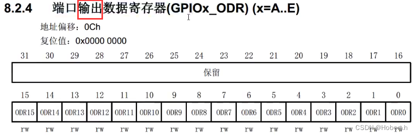
内核可以通过APB2对寄存器进行读写,寄存器都是32位的,但每个引脚端口只有16位
驱动器用于增加信号的驱动能力
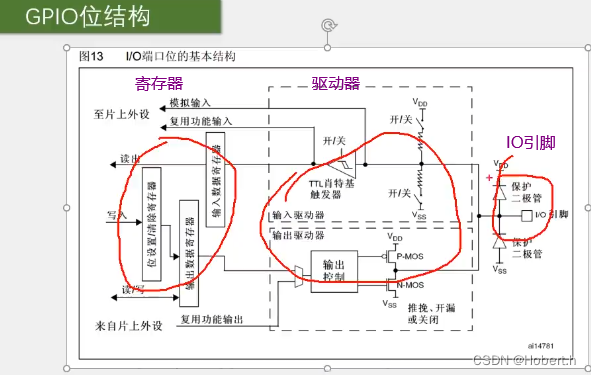
二.具体电路结构
-------------------------------------------------------------------------------------------------------------------------

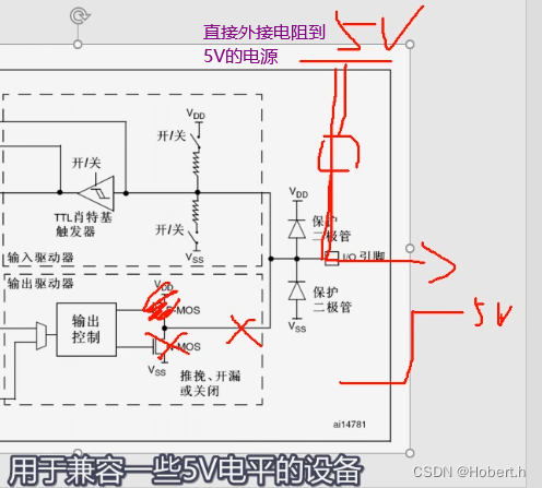
保护二极管:
如果IO引脚输入电压高于3.3V,那么上面的二极管就会导通,电流会流到VDD
如果IO引脚输入电压低于0V,那么下面的二极管就会导通,电流会流到VSS
如果IO引脚输入电压在0-3.3V之间,那么电流会流到内部电路
这里设置的上下拉电阻,是为了防止设备进入浮空状态,
在使用浮空输入是,端口一定要接上一个连续的驱动源,不能出现悬空状态
-------------------------------------------------------------------------------------------------------------------------
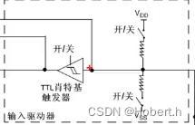
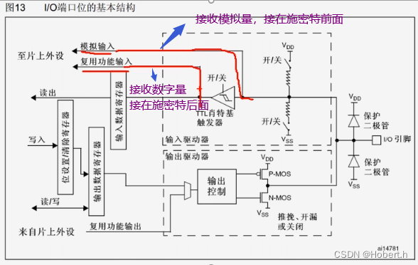
施密特触发器的执行逻辑
如果输入电压大于某一阈值,输出就会瞬间升为高电平
如果输入电压小于某一阈值,输出就会瞬间降为低电平

-------------------------------------------------------------------------------------------------------------------------
推挽模式
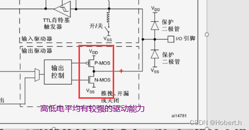 所以可以叫强推输出模式
-------------------------------------------------------------------------------------------------------------------------
开漏模式
上面的MOS管会断开,所以只有低电平有驱动能力,高电平没有驱动能力,可以作为通信协议的驱动方式,I2C通信的引脚就是使用的开漏模式,可以避免多个设备的干扰
开漏模式还可以输出5V的电平信号
-------------------------------------------------------------------------------------------------------------------------
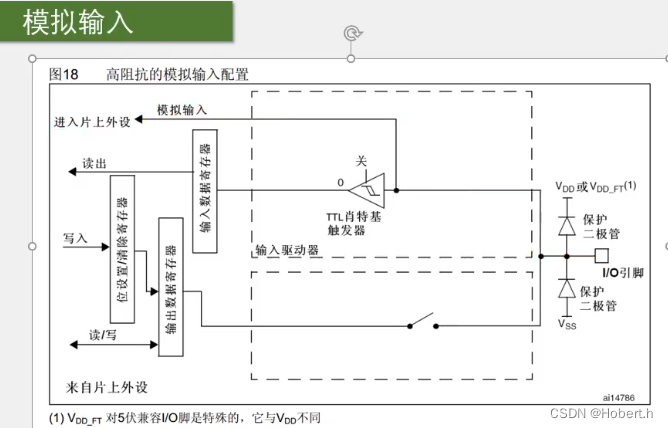
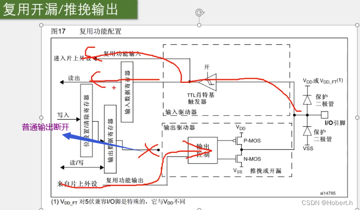
三.具体的GPIO模式
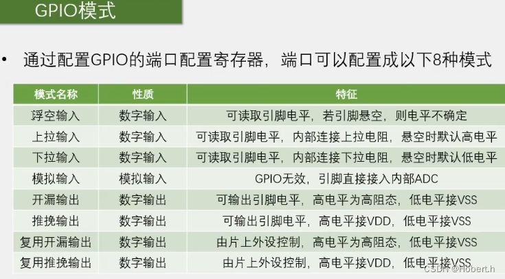
一个端口只能有一个输出,但可以有多个输入


四.GPIO的寄存器
GPIO配置寄存器
每个端口的模式由4位进行配置,16个端口需要64位,所以配置寄存器有2个(CRL,CRH)

目的是为了低功耗和稳定性
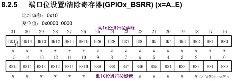
可以实现同时对多个端口进行位设置和位清除,可以保障位设置和位清除的同步性
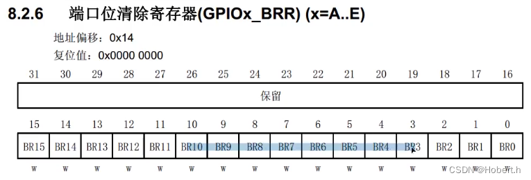
但BSRR也可以结合BRR进行先位设置再位清除

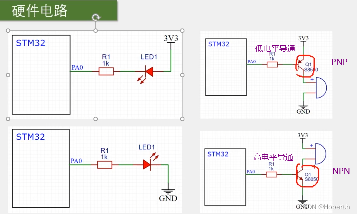
五.stm32外部的设备和电路

六.代码实现
一.点亮LED
#include "stm32f10x.h"                  // Device header
//#include "Delay.h"
int main()
{
    GPIO_InitTypeDef GPIO_InitStructure;
    RCC_APB2PeriphClockCmd(RCC_APB2Periph_GPIOA,ENABLE);
    GPIO_InitStructure.GPIO_Mode=GPIO_Mode_Out_PP;
    GPIO_InitStructure.GPIO_Pin=GPIO_Pin_0;
    GPIO_InitStructure.GPIO_Speed=GPIO_Speed_50MHz;
    GPIO_Init(GPIOA,&GPIO_InitStructure);
    while(1)
    {
//        GPIO_WriteBit(GPIOA,GPIO_Pin_0,Bit_RESET);
        GPIO_WriteBit(GPIOA,GPIO_Pin_0,Bit_SET);

    }

}
二.LED闪烁
#include "stm32f10x.h"                  // Device header
#include "Delay.h"
int main()
{
	GPIO_InitTypeDef GPIO_InitStructure;
	RCC_APB2PeriphClockCmd(RCC_APB2Periph_GPIOA,ENABLE);
	GPIO_InitStructure.GPIO_Mode=GPIO_Mode_Out_PP;
	GPIO_InitStructure.GPIO_Pin=GPIO_Pin_0;
	GPIO_InitStructure.GPIO_Speed=GPIO_Speed_50MHz;
	GPIO_Init(GPIOA,&GPIO_InitStructure);
	while(1)
	{
		GPIO_ResetBits(GPIOA,GPIO_Pin_0);
		Delay_ms(500);

		GPIO_SetBits(GPIOA,GPIO_Pin_0);
		Delay_ms(500);


		GPIO_WriteBit(GPIOA,GPIO_Pin_0,Bit_RESET);
		Delay_ms(500);
		GPIO_WriteBit(GPIOA,GPIO_Pin_0,Bit_SET);
		Delay_ms(500);

		GPIO_WriteBit(GPIOA,GPIO_Pin_0,(BitAction)0);
		Delay_ms(500);
		GPIO_WriteBit(GPIOA,GPIO_Pin_0,(BitAction)1);
		Delay_ms(500);
	}

}
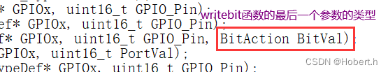
三种LED闪烁书写方式, 最后一种的0和1要转换类型
三.LED流水灯

#include "stm32f10x.h" // Device header
#include "Delay.h"
int main(void)
{
/*开启时钟*/
RCC_APB2PeriphClockCmd(RCC_APB2Periph_GPIOA, ENABLE); //开启GPIOA的时钟
//使用各个外设前必须开启时钟,否则对外设的操作无效
/*GPIO初始化*/
GPIO_InitTypeDef GPIO_InitStructure; //定义结构体变量
GPIO_InitStructure.GPIO_Mode = GPIO_Mode_Out_PP; //GPIO模式,赋值为推挽输出模式
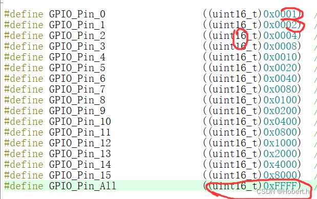
GPIO_InitStructure.GPIO_Pin = GPIO_Pin_All; //GPIO引脚,赋值为第0号引脚
GPIO_InitStructure.GPIO_Speed = GPIO_Speed_50MHz; //GPIO速度,赋值为50MHz
GPIO_Init(GPIOA, &GPIO_InitStructure); //将赋值后的构体变量传递给GPIO_Init函数
//函数内部会自动根据结构体的参数配置相应寄存器
//实现GPIOA的初始化
/*主循环,循环体内的代码会一直循环执行*/
while (1)
{
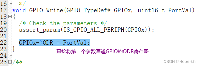
GPIO_Write(GPIOA,~0x0001);//0000 0000 0000 0001
Delay_ms(100);
GPIO_Write(GPIOA,~0x0002);//0000 0000 0000 0010
Delay_ms(100);
GPIO_Write(GPIOA,~0x0004);//0000 0000 0000 0100
Delay_ms(100);
GPIO_Write(GPIOA,~0x0008);//0000 0000 0000 1000
Delay_ms(100);
GPIO_Write(GPIOA,~0x0010);//0000 0000 0001 0000
Delay_ms(100);
GPIO_Write(GPIOA,~0x0020);//0000 0000 0010 0000
Delay_ms(100);
GPIO_Write(GPIOA,~0x0040);//0000 0000 0100 0000
Delay_ms(100);
GPIO_Write(GPIOA,~0x0080);//0000 0000 1000 0000
Delay_ms(100);
}
}四.蜂鸣器
使用GPIOB_PB12端口
#include "stm32f10x.h"                  // Device header
#include "Delay.h"
int main()
{
	GPIO_InitTypeDef GPIO_InitStructure;
	RCC_APB2PeriphClockCmd(RCC_APB2Periph_GPIOB,ENABLE);
	GPIO_InitStructure.GPIO_Mode=GPIO_Mode_Out_PP;
	GPIO_InitStructure.GPIO_Pin=GPIO_Pin_12;
	GPIO_InitStructure.GPIO_Speed=GPIO_Speed_50MHz;
	GPIO_Init(GPIOB,&GPIO_InitStructure);
	while(1)
	{
		GPIO_ResetBits(GPIOB,GPIO_Pin_12);
		Delay_ms(100);

		GPIO_SetBits(GPIOB,GPIO_Pin_12);
		Delay_ms(100);
		GPIO_ResetBits(GPIOB,GPIO_Pin_12);
		Delay_ms(100);

		GPIO_SetBits(GPIOB,GPIO_Pin_12);
		Delay_ms(700);

	}

}