process control 化学工程 需要用到MATLAB的Simulink功能
所有问题需要的matlab simulink 模型
WeChat: ye1-6688
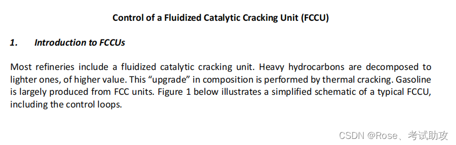
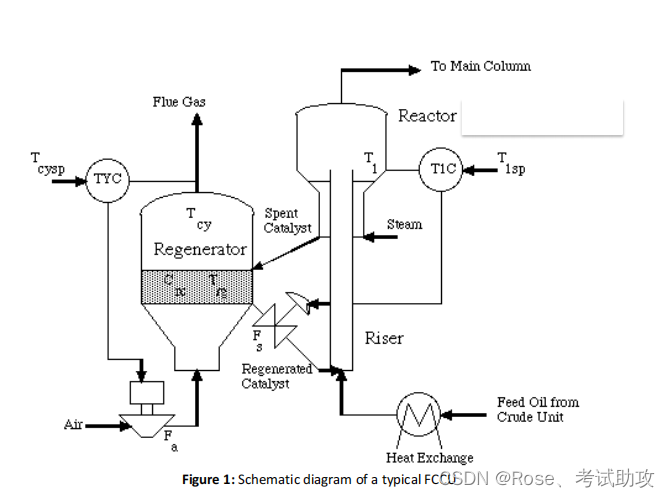
The riser tube brings in contact the recirculating catalyst with the feed oil, which then vaporizes and
splits to lighter components as it flows up the riser, forming the desired gasoline fraction. Coke is a
byproduct of this process, which deposits on the catalyst reducing its activity. The spent catalyst is
separated from the rest of the mixture in the ‘reactor’ unit shown in Figure 1, which is practically a
separator of staged cyclones and is only called reactor for historical reasons. In a part of the unit not
shown in the Figure, steam is used for the stripping of volatile components from the catalyst. The latter
is then fed to the regenerator, where air is used to burn off the coke. Typically, partial combustion is
employed, although some units do perform complete combustion. The regenerated catalyst is
recirculated back to the FCCU by mixing it with the inlet feed oil.
2. The control problem
FCCUs are considered to be complex units and give rise to VERY challenging control problems. The
selection of manipulated and control variables as well their pairing is crucial.
In this case, the important measured variables are chosen to be the reactor temperature/riser outlet
temperature (T1), the regenerator gas (cyclone) temperature (Tcy) and the regenerator bed
temperature (Trg). The manipulated variables are the catalyst recirculation rate (Fs) and the
regenerator air rate (Fa).
In Figure 1, you can see the pairing of the variables: the reactor temperature/riser outlet temperature
(T1) can be controlled by manipulating the catalyst recirculation rate (Fs), whereas the regenerator gas
temperature (Tcy) can be regulated using the regenerator air rate (Fa). Clearly changes in each of the
inputs will afeect all outputs. The regenerator bed temperature (Trg) is not part of any control loop, but
it is a quantity that needs to be monitored.
3. The assignment
You will focus on designing a controller to control the cyclone Temperature (Tcy) by manipulating the
regenerator air rate (Fa). You will need to answer all the questions a control engineer needs to answer
while designing a control loop. The detailed realistic process is given in the Simulink file, containing a
quite detailed model of the FCCU. You can download the Simulink model from blackboard. All groups
should download file FCCU.mdl.
**Be careful. When you download the file your system might automatically rename it to something
like FCCU(1).mdl or similar. SIMULINK will not be able to run it and will give you an error. You will
need to rename it to its original name. ***
The region of operation of the unit is the vicinity around the steady-state given in the .mdl file. You need
to design a robust working controller for the chosen input/output pair. To help you in this process a
number of tasks are provided below
a. Investigate the dynamics of your system and extract an approximate first order transfer function
model with delay. This will be used to tune your controller in subsequent tasks. Discuss and justify
the procedures you follow as well as all your findings.
b. Demonstrate the robustness of the approximate model you obtained in (a) by illustrating that it
works for a range of different (not only step) inputs. Illustrate, discuss and justify all your findings.
c. Design stable controllers based on your approximate system using different tuning methodologies:
(i) Ziegler-Nichols (PI & PID)
(ii) Cohen-Coon (PI & PID)
(iii) IMC, where the delay is approximated by
a. 1st order Taylor expansion
b. Padé
Test your controllers on the real system (i.e. the detailed model). Check if they produce a stable output
and justify your findings appropriately by simulating the closed-loop system you have designed using
appropriate step changes to the set point. Clearly show all your work.
d. Provide a meaningful comparison of the controllers you have designed, by discussing and
comparing their features. Choose your best two controllers (to use in parts f and g below) and
explain why they are the best.
e. Explain clearly which units of your block use deviation variables as inputs and outputs and which
use real variables. Use appropriate control block diagrams to aid your explanation(s).
f. Using your two best controllers(chosen in part d): Run the closed-loop simulation of the real system
with these best controllers and plot the inputs as well as Trg as a function of time. Do you think the
values of the inputs and of Trg are physical/realistic? If they are not you need to re-tune your
controllers so that they produce physical/realistic outputs. Clearly justify your work and answers.
g. For your two best controllers (from part d) you need to find:
i. What is the range of set points that your controller is trustworthy, i.e. all inputs and outputs
remain physical/realistic and the set point is satisified.
ii. For the nominal (unit step) set point, what is the range of input disturbances that your controller
can reject, while all inputs and outputs remain realistic? Clearly justify all your answers.
Remarks:
Note that the final time of all simulations has to be chosen so that it allows the system to reach steadystate.
References
Lee, W., and V.W. Weekman, “Advanced Control Practice in the Chemical Process Industry: A View from
Industry”, AIChE J., 22, 27 (1976).
Grosdidier, P., A. Mason, A. Aitolahti, P. Heinonen, and V. Vanhamaki, “FCC Unit Reactor-Regenerator
Control”, Computers Chem. Eng., 17, 165 (1993).